Elecraft KRX3 User Manual
Page 42
42
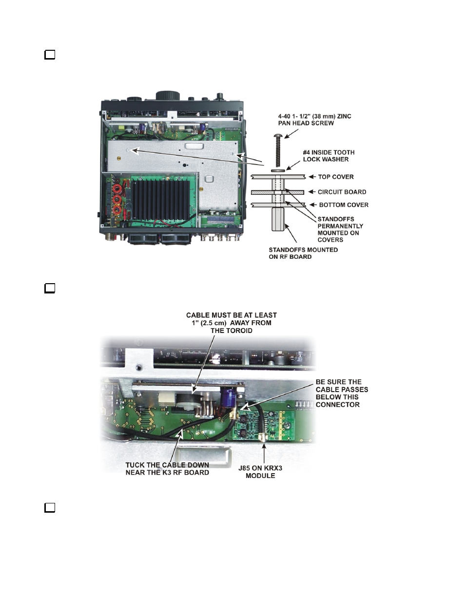
Secure the KRX3 module to the two standoffs using 1-1/2” (38 mm) 4-40 pan head screws as shown in
Figure 51. The screws will pass through the internal standoffs and circuit board inside the enclosure and screw
into the standoffs you mounted on the K3 RF board earlier. Place an inside tooth lock washer under each screw
head.
Figure 51. Installing the KRX3 Enclosure.
Position the cable between J84 on the Aux KSYN3 board and J85 on the KRX3 module as shown in
Figure 52. This is essential to ensure the proper signal isolation between the main and sub receivers.
Figure 52. Routing the Cable to J85.
Double check all the TMP cables to ensure none were dislodged from their connectors or kinked tightly
while positioning the KRX3 module. The two cables attached to the K3 RF board are not visible, but should not
have been disturbed by installing the KRX3. Pay particular attention to cables attached to the KREF3 and
KSYN3 boards. If needed, you can replace a dislodged cable without removing the KRX3 module using needle
nose pliers to hold the finger grip part of the connector.