Caution – Elecraft KRX3 User Manual
Page 25
25
Install the Auxiliary KSYN3 board on the back of the front panel shield between the KREF3 board and the
side panel. Use the hardware exactly as shown in Figure 28. This is most easily done as follows:
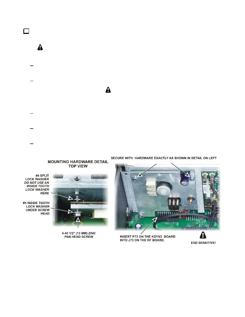
You may find that it helps to elevate the front of the K3 so that the lock washer on the
screw (left side of Figure 28) tends to slide toward the Aux KSYN3 board.
Place an inside tooth lock washer over each 1/2” (13 mm) pan head screw, then place the screw in the
hole in the KSYN3 board.
While holding the screws in place, add a split lock washer to each screw on the back side of the board.
CAUTION
Be sure you use split lock washers on the back of the board. Inside tooth lock
washers may short out nearby circuit traces.
Hold the board with the screws and washers in position by lightly pinching the corners of the board with
your thumbs over the screw heads and index fingers holding the split lock washers in place on the back.
Position the board to mate P73 on with J74 on the RF board. Be sure you have the connectors properly
aligned and mate them fully so the screws line up with the PEM nuts on the front panel shield.
Thread each screw into the PEM nut on the front panel shield. Be sure the split lock washer is still in
place between the board and the PEM nut.
Figure 28. Installing the Aux KSYN3 Board.