Caution – Elecraft KRX3 User Manual
Page 14
14
CAUTION
Before continuing on with the next step, be sure you have removed the three top Front
Panel Assembly screws shown in Figure 7. You may bend and damage the front panel or
shield assemblies if the screws are not removed!
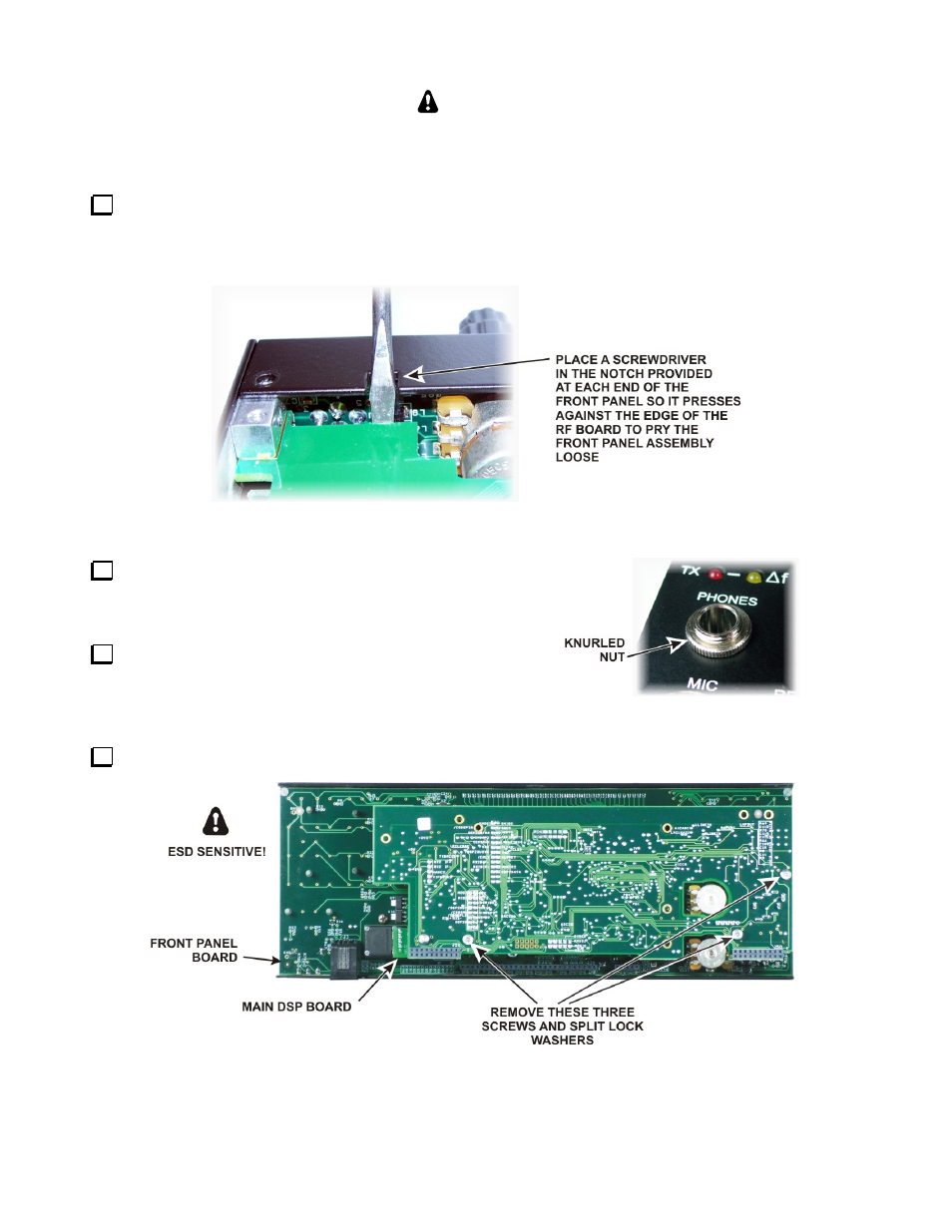
Use a screwdriver in the pry tool openings to press back against the circuit board while pushing the lip on
the front panel assembly toward the front as shown in Figure 9. Do not insert the screwdriver any farther
than necessary to avoid damaging components! When you have the front panel assembly free, set the main
chassis aside in a safe place.
Figure 9. Separating the Front Panel Assembly from the Chassis.
On the front panel, remove the knurled nut from the
PHONES jack directly above the MIC connector. Be
very careful not to scratch the paint on the front panel.
Place the front panel assembly face down on a
smooth, clean soft surface to avoid scratches to the LCD
cover or front panel paint
Figure 10. Phones Jack Knurled Nut.
Remove the three screws and split lock washers shown in Figure 11.
Figure 11. Removing Main DSP Board.