Final assembly – Elecraft KRX3 User Manual
Page 43
43
Final Assembly
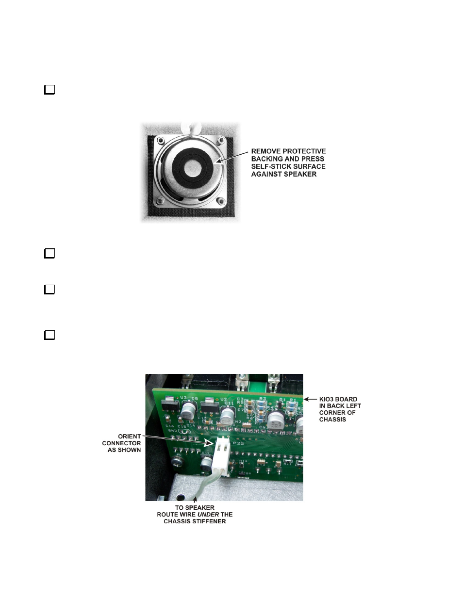
Remove the covering over the self-adhesive side of the foam pad and press the adhesive side against the
speaker magnetic shield (see Figure 53). The pad will compress between the loudspeaker and the top of the
KRX3enclosure when the cover is installed.
Figure 53. Attaching the Speaker Pad.
If your k3 is equipped with the K144XV 2-meter option, refer to the K144XV manual to reconnect the
cables and remount the module on the left side panel. Route the power wire as shown in the K144XV manual so
it won’t be trapped between the speaker pad and the top of the KRX3 module. .
Replace the chassis stiffener bar using two 4-40 3/16” (4.8 mm) black flat head screws at the ends. If the
KPA3 is installed, attach the stiffener to the shield using two 4-40 1/4” (6.4 mm) screws with lock washers
under the screws. (Some stiffener bars do not have threaded PEM nuts attached. In that case, secure the screws
with 4-40 nuts and place the lock washers under the nuts).
Hold the top cover above the K3, route the speaker wire under the stiffener bar and plug it into P25 on the
KIO3 board at the left rear of the K3 as shown in Figure 54. If you have the K144XV 2-meter module installed,
there is an indentation in the top of the module where you can pass the speaker wire connector under the chassis
stiffener.
Figure 54. Connecting Speaker Cable.