Elecraft KRX3 User Manual
Page 28
28
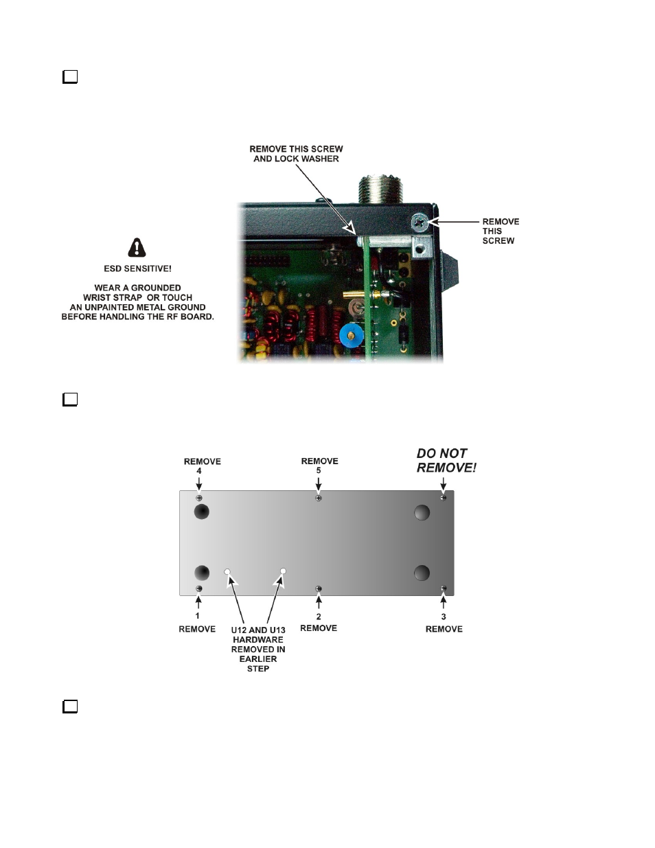
Remove the screw holding the KANT3 (or, if installed, the optional KAT3) board to the standoff and the
screw holding the 2D fastener to the rear panel near the SO239 antenna connector shown in Figure 31. Do not
lose the lock washer inside the K3. It is easier to keep the hardware from falling inside if you set the K3 on its
side feet and remove the screw and lock washer holding the KANT3 or KAT3 board first, then set it on its
bottom feet and remove the flat head screw from the 2D fastener.
Figure 31. Removing Side Panel Hardware, Part 1.
Remove the five screws shown in Figure 32 from the right side panel to release it. Screw 5, which holds the
end of the stiffener bar, already will be out if you’re performing the initial installation of the KRX3. The side
panel will lift off with the 2D fastener and standoff shown in Figure 31 attached.
Figure 32. Removing Side Panel Hardware, Part 2.
Remove the dummy plug from the AUX RF connector hole in the back panel directly below the SO-239
ANT2 connector. The plug is released by squeezing two tabs on opposite sides.