Thermcraft XST-3-0-36-3V User Manual
Page 57
Operation
Installation and Operation Handbook
2408 and 2404 Controller
2-9
Parameter names
In the navigation diagram, each box shows the display for a selected parameter.
The Operator parameter tables, later in this chapter, list all the parameter names and their
meanings.
The navigation diagram shows all the parameters that can, potentially, be present in the
controller. In practice, a limited number of them appear, as a result of the particular
configuration.
The shaded boxes in the diagram indicate parameters that are hidden in normal operation. To
view all the available parameters, you must select Full access level. For more information
about this, see Chapter 3, Access Levels.
Parameter displays
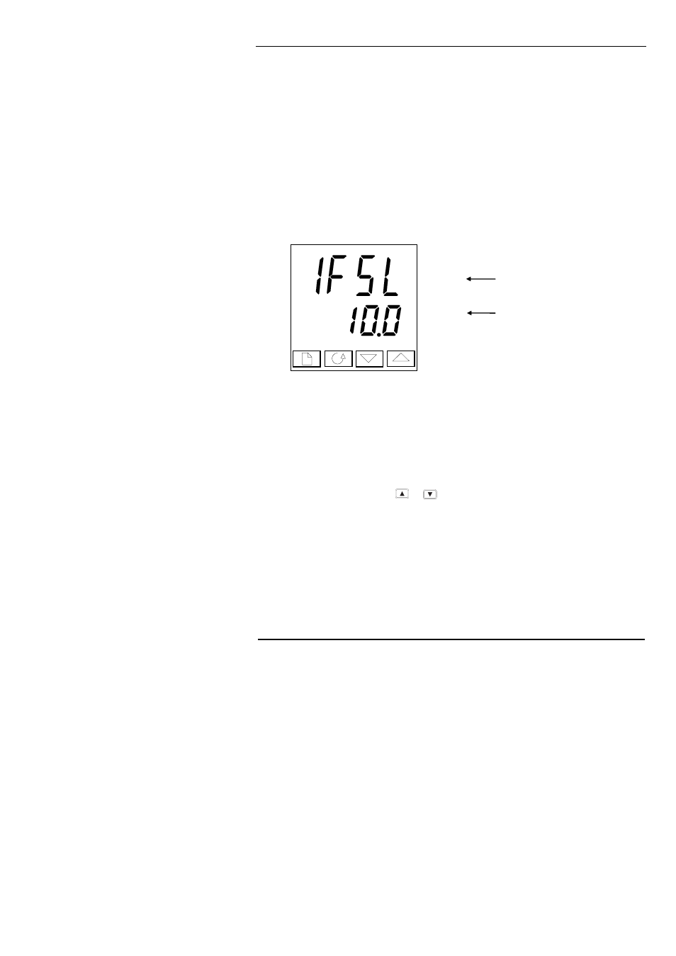
Figure 2-6 Typical parameter display
Parameter displays show the controller’s current settings. The layout of parameter displays is
always the same: the upper readout shows the parameter name and the lower readout its value.
In the above example, the parameter name is
1FSL (indicating Alarm 1, full scale low), and
the parameter value is
10.0.
To change the value of a parameter
First, select the required parameter.
To change the value, press either
or
. During adjustment, single presses change the
value by one digit.
Keeping the button pressed speeds up the rate of change.
Two seconds after releasing either button, the display blinks to show that the controller has
accepted the new value.
Parameter name
Parameter value