Thermcraft XST-3-0-36-3V User Manual
Page 256
Load Current Monitoring and Diagnostics
Installation and Operation Handbook
8-2
2416 Controller
1.
8.1
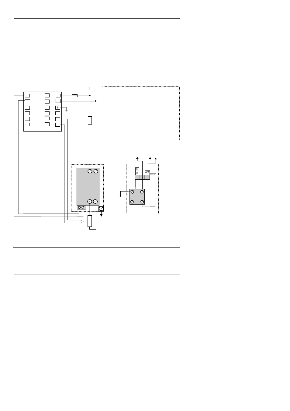
EXAMPLE WIRING DIAGRAM (FOR MODE 1 & 2 OPERATION)
Hardware Required
1. Eurotherm SSR type TE10/PDS2 OR
2. Eurotherm intelligent current transformer type PD/CTX + contactor or zero voltage
switching SSR
2416 controller configured for PDS mode 2 option using logic output. This module must be
fitted in module position 1. (order code M2).
Figure D.1 Connections for Mode 1 & 2
Warning!
Take care that the controller is correctly wired for the mode of operation which is configured.
Failure to do so may be hazardous in some situations.
Heater
Heater
power fuse
(load
dependent)
L
N
Controller
Fuse 2A(T)
L
Alternative current regulator
arrangements:-
The Eurotherm TE10/PDS2 contains
integral power regulator and intelligent
PDCTX
The PDCTX can be supplied separately for
use with any SSR or logic thyristor unit as
shown in the diagram below.
The output drive capability of the PDCTX is
5V at 7mA maximum
PDCTX
Intelligent
Current
Transformer
Logic input
SSR
+
+ Red
- Black
-
To
Heater
To L
To logic output
1A & 1B
TE10 Solid
State
Relay
T/C
+
-
L N
N
V+
V-
1B
1A
C
O
M
M
S
1
+
-
+
PV
-
This
represents a
single turn
through the
CT