Thermcraft XST-3-0-36-3V User Manual
Page 38
Installation
Installation and Operation Handbook
1-8
2408 and 2404 Controller
Two terminal modules
Note: Module 1 is connected to terminals 1A and 1B
Module 2 is connected to terminals 2A and 2B
Module 3 is connected to terminals 3A and 3B.
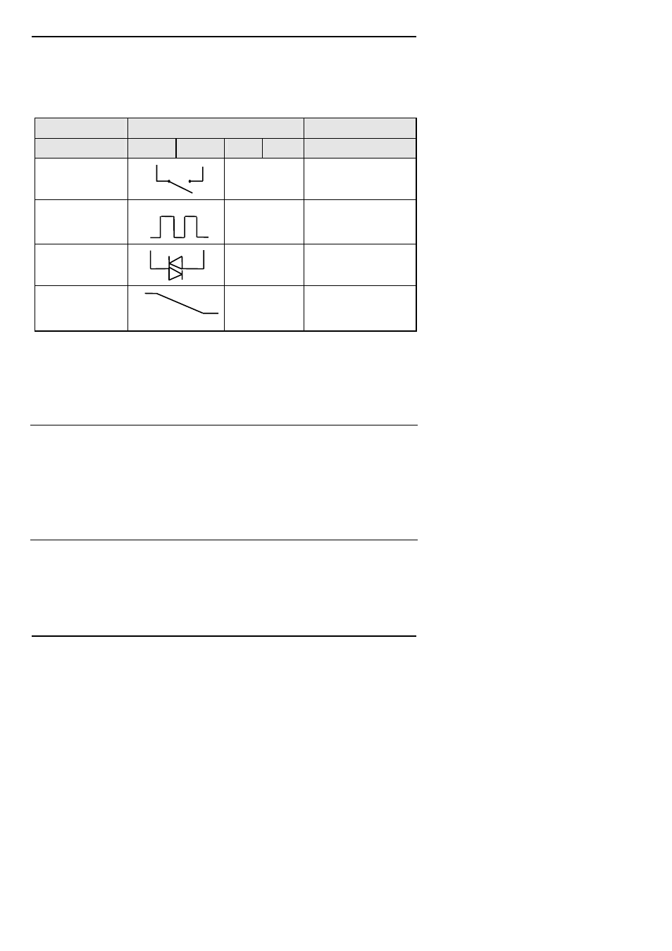
Terminal identity
Module type
A
B
C
D
Possible functions
Relay: 2-pin
(2A, 264 Vac max.)
Unused Heating,
cooling,
alarm,
program event, valve
raise, or valve lower
Logic - non-isolated
(18Vdc at 20mA)
+
−
Unused Heating,
cooling,
PDSIO
mode 1, PDSIO mode 2,
program event
Triac
(1A, 30 to 264Vac)
Unused
Heating,
cooling,
program event, valve
raise, or valve lower
DC output:
- non-isolated
(10Vdc, 20mA max.)
+
−
Unused
Heating, or cooling, or
retransmission of PV,
setpoint, or control output
Table 1-1 Two terminal module connections
Snubbers
The relay and triac modules have an internal 15nF/100
Ω ‘snubber’ connected across their
output, which is used to prolong contact life and to suppress interference when switching
inductive loads, such as mechanical contactors and solenoid valves.
WARNING
When the relay contact is open, or the triac is off, the snubber circuit passes 0.6mA at
110Vac and 1.2mA at 240Vac. You must ensure that this current, passing through the
snubber, will not hold on low power electrical loads. It is your responsibility as the
installer to ensure that this does not happen. If the snubber circuit is not required, it can
be removed from the relay module (BUT NOT THE TRIAC) by breaking the PCB track
that runs crosswise, adjacent to the edge connectors of the module. This can be done by
inserting the blade of a small screwdriver into one of the two slots that bound it, and
twisting.
Line Load