Thermcraft XST-3-0-36-3V User Manual
Page 119
Installation and Operation Handbook
Configuration
2408 and 2404 Controller
6-21
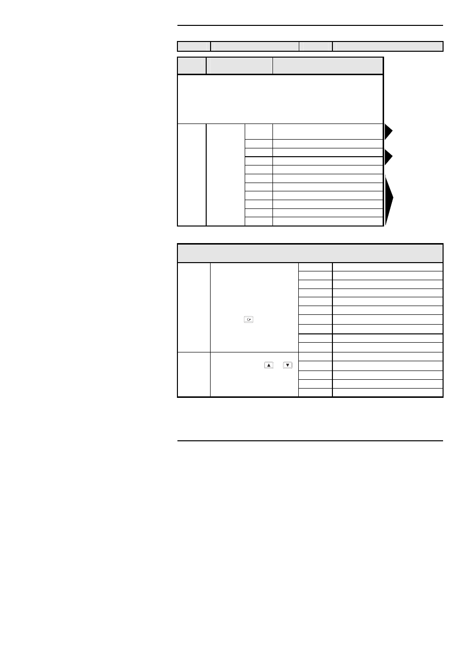
Name
Description
Values
Meaning
CAL
Calibration
In this mode you can
1. Calibrate the instrument using a mV source -
rcAL
or ref source
cal.
2. Offset the calibration to account for errors in actual sensor
measurement and a ref sensor -
UCAL
or user calibration
3. Return to factory set calibration -
FACT
or factory set calibration.
rcAL Calibration
point
nonE No calibration
PV
Calibrate main Process Value input.
PV.2
Calibrate DC input, or PV 2.
1A.Hi
Calibrate DC output high - Module 1
1A.Lo
Calibrate DC output low - Module 1
2A.Hi
Calibrate DC output high - Module 2
2A.Lo
Calibrate DC output low - Module 2
3A.Hi
Calibrate DC output high - Module 3
3A.Lo
Calibrate DC output low - Module 3
I
NPUT
C
ALIBRATION
For ‘
CAL
’ = ‘
PV’, or ‘PV.2
’, the following parameters apply.
PV
PV Calibration Value
IdLE
Idle
mv.L
Select 0mV as the calibration point
mv.H
Select 50mV as the calibration point
V 0
Select 0Volt as the calibration point
1. Select calibration value
V 10
Select 10V as the calibration point
2. Apply specified input
CJC
Select 0
o
C CJC calibration point
3. Press to step to ‘
GO’ rtd
Select 400
Ω as the calibration point
HI 0
High impedance: 0Volt cal’n point
HI 1.0 High impedance: 1.0 Volt cal’n point
See Note below.
FACt
Restore factory calibration
GO
Start calibration
no
Waiting to calibrate PV point
Select ‘
YES’ with
or
YES
Start calibration
Wait for calibration to
buSy
Busy calibrating
complete.
donE
PV input calibration completed
FAIL
Calibration failed
Note. When a DC input module is installed for the first time, or there is a requirement to change one,
then the microprocessor in the controller needs to read the factory calibration data stored in the module.
Select ‘
FACt’ as the calibration value. Step to ‘GO’ and start calibration.
Goto User
calibration table-
See also chapter 7
Go to input
Calibation table
Go to
DC Output
Calibration
table