Thermcraft XST-3-0-36-3V User Manual
Page 43
Installation and Operation Handbook
Installation
2408 and 2404 Controller
1-13
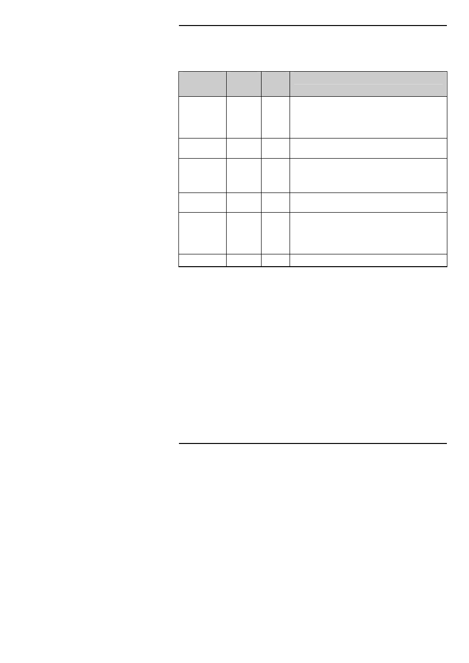
DeviceNet
Instruments fitted with software versions 4 onwards can be fitted with DeviceNet
communications. The following shows the wiring connections for DeviceNet.
Terminal
Reference
CAN
Label
Color
Chip
Description
HA
V+
Red
DeviceNet network power positive terminal. Connect
the red wire of the DeviceNet cable here. If the
DeviceNet network does not supply the power,
connect to the positive terminal of an external 11-25
Vdc power supply.
HB
CAN_H
White
DeviceNet CAN_H data bus terminal. Connect the
white wire of the DeviceNet cable here.
HC
SHIELD
None
Shield/Drain wire connection. Connect the
DeviceNet cable shield here. To prevent ground
loops, ground the DeviceNet network in only one
location.
HD
CAN_L
Blue
DeviceNet CAN_L data bus terminal. Connect the
blue wire of the DeviceNet cable here.
HE
V-
Black
DeviceNet network power negative terminal.
Connect the black wire of the DeviceNet cable here.
If the DeviceNet network does not supply the power,
connect to the negative terminal of an external 11-25
Vdc power supply.
HF
Connect to instrument earth
Note: Power taps are recommended to connect the DC power supply to the DeviceNet trunk
line. Power taps include:
• A Schottky Diode to connect the power supply V+ and allows for multiple power
supplies to be connected.
• 2 fuses or circuit breakers to protect the bus from excessive current which could damage
the cable and connectors.
• The earth connection, HF, to be connected to the main supply earth terminal.