Amps, Amps ---- disp – Thermcraft XST-3-0-36-3V User Manual
Page 150
Load Current Monitoring and Diagnostics Installation and Operation Handbook
D-4 2408 and 2404 Controller
OPERATION
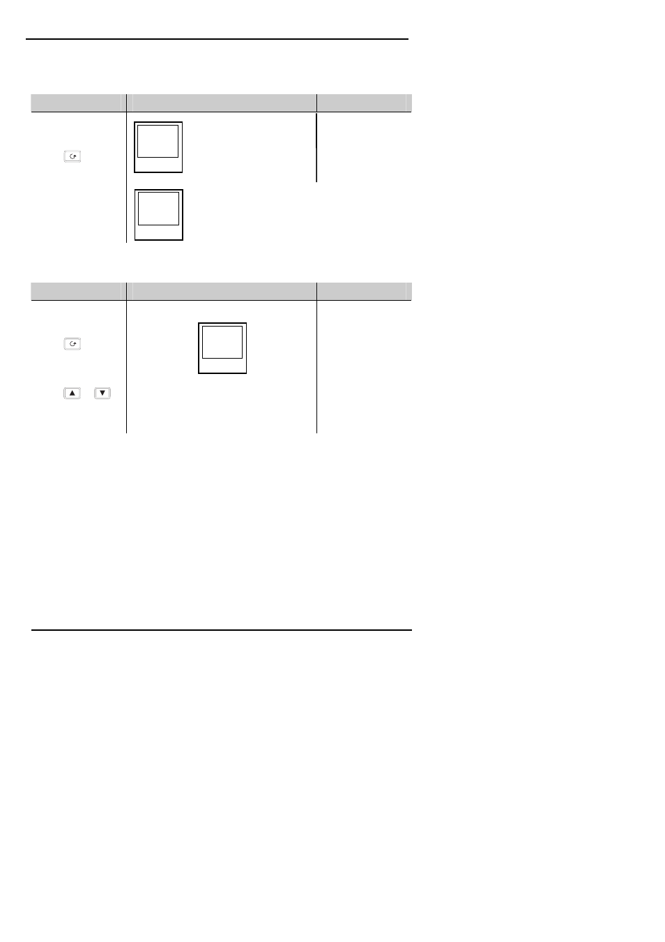
To Read Load Current (modes 2 and 5 only)
Do This
This Is The Display You Should See
Additional Notes
From the ‘
InFo’ list
Press
until
AmPS is shown in
the upper display
It will revert to the
HOME display after
45 seconds or 10
seconds if an alarm
is present
To Display Load Current Continuously in the Lower Readout (modes 2 and 5
only)
Do This
This Is The Display You Should See
Additional Notes
From the ‘HOME’
display, Figure 1.4,
Press
until
diSP is shown in
the upper display
Press
or
until
AmPS is
displayed in the
lower display
Current will be
displayed in the
lower readout
continuously when
the controller reverts
to the HOME
display, see also
‘Display Modes’
below.
Display Modes
SSR RMS On State Current
This is the default state when high or low current alarms are configured. The load current
displayed is the steady state true rms current measured during the ON period.
The minimum on times are:-
Mode 2
0.1second
Mode 5
3 seconds
Meter Mode
Meter mode applies to mode 5 only. If low current alarms are not configured the current
displayed is a filtered instantaneous RMS value. This behaves like a damped analogue meter.
It may be used in applications where the current sensor is not linked to control, for example,
telemetry, indication.
AmPS
5
AmPS
----
diSP
AmPS
Current will be displayed in
the lower readout. See
also ‘Display Modes’
below.
This display will be shown if:
I. The controller is unable to resolve the reading
II. The controller is obtaining a reading
III. The measurement has timed out i.e. current has
not flowed for 15 seconds, in mode 2.