Thermcraft XST-3-0-36-3V User Manual
Page 199
Installation and Operation Handbook
Operation
2416 Controller
2-15
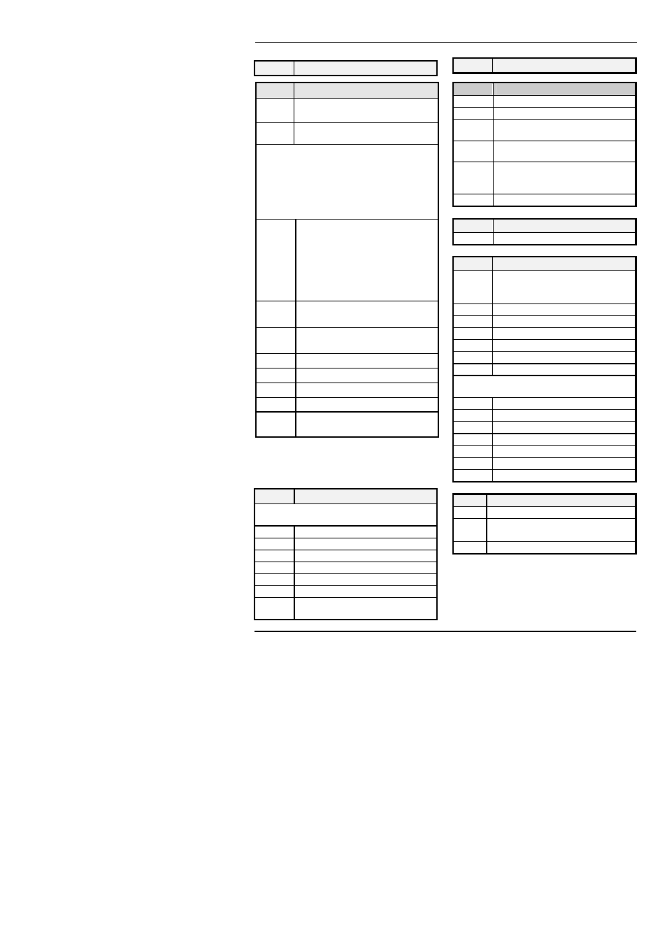
Name Description
iP
Input list
FiLt IP filter time constant (0.0 - 999.9
seconds).
Emis Emissivity - when the input is
configured for a pyrometer
The next 3 parameters appear only if User
Calibration has been enabled. (Refer to
Chapter 7.) By default they are hidden
when in Operator level. To prevent
unauthorised adjustment, we recommend
that they are only made available in
FuLL
access level.
CAL
‘
FACt’ - reinstates the factory
calibration and disables User
calibration. Next 2 parameters
will not appear.
‘
USEr’ - reinstates any previously
set User calibration. All
parameters below now appear.
CAL.s Selected
calibration
point
−
‘
nonE’, ’iP1.L’, ‘ip1.H’
AdJ *
User calibration adjust, if
CAL.s =
’
iP1.L’, ‘ip1.H’
OFS.1
IP calibration offset
mV.1
IP measured value (at terminals)
CJC.1
IP Cold Junction Compensation
Li.1
IP Linearised Value
PV.SL PV Select. Not operational in
2416
* Do not make adjustments using the
AdJ
parameter unless you wish to change the
controller calibration.
oP
Output list
Does not appear if Motorised Valve control
configured.
OP.Lo
Low power limit (%)
OP.Hi
High power limit (%)
OPrr
Output Rate Limit (% per sec)
FOP
Forced output level (%)
CYC.H
Heat cycle time (0.2S to 999.9S)
hYS.H
Heat hysteresis (display units)
ont.H
Heat output min. on-time (secs)
Auto (0.05S), or 0.1 - 999.9S
Name Description
op
Output list continued
CYC.C
Cool cycle time (0.2S to 999.9S)
hYS.C
Cool hysteresis (display units)
ont.C
Cool output min. on-time (secs)
Auto (0.05S), or 0.1 - 999.9S
HC.db
Heat/cool deadband (display
units)
End.P Power level in programmer in end
segment. This is a single
parameter for all programs
Sb.OP
Sensor Break Output Power (%)
cmS
Comms list
Addr
Communications Address
inFo
Information list
diSP
Configure lower readout of Home
display to:
nonE, Std, Lcur,
OP, Stat, PrG.t
LoG.L
PV minimum
LoG.H
PV maximum
LoG.A
PV mean value
Log.t
Time PV above Threshold level
Log.v
PV Threshold for Timer Log
rES.L
Logging Reset - ‘
YES/no’
The following set of parameters is for
diagnostic purposes.
mCt
Processor utilisation factor
w.OP
Working output
FF.OP
Feedforward component of output
VO
PID output to motorised valve
P OP
Proportional component of output
I OP
Integral component of output
d OP
Derivative component of output
ACCS Access List
codE Access password
Goto Goto level - OPEr, FuLL, Edit or
conF
ConF Configuration password