Thermcraft XST-3-0-36-3V User Manual
Page 195
Installation and Operation Handbook
Operation
2416 Controller
2-11
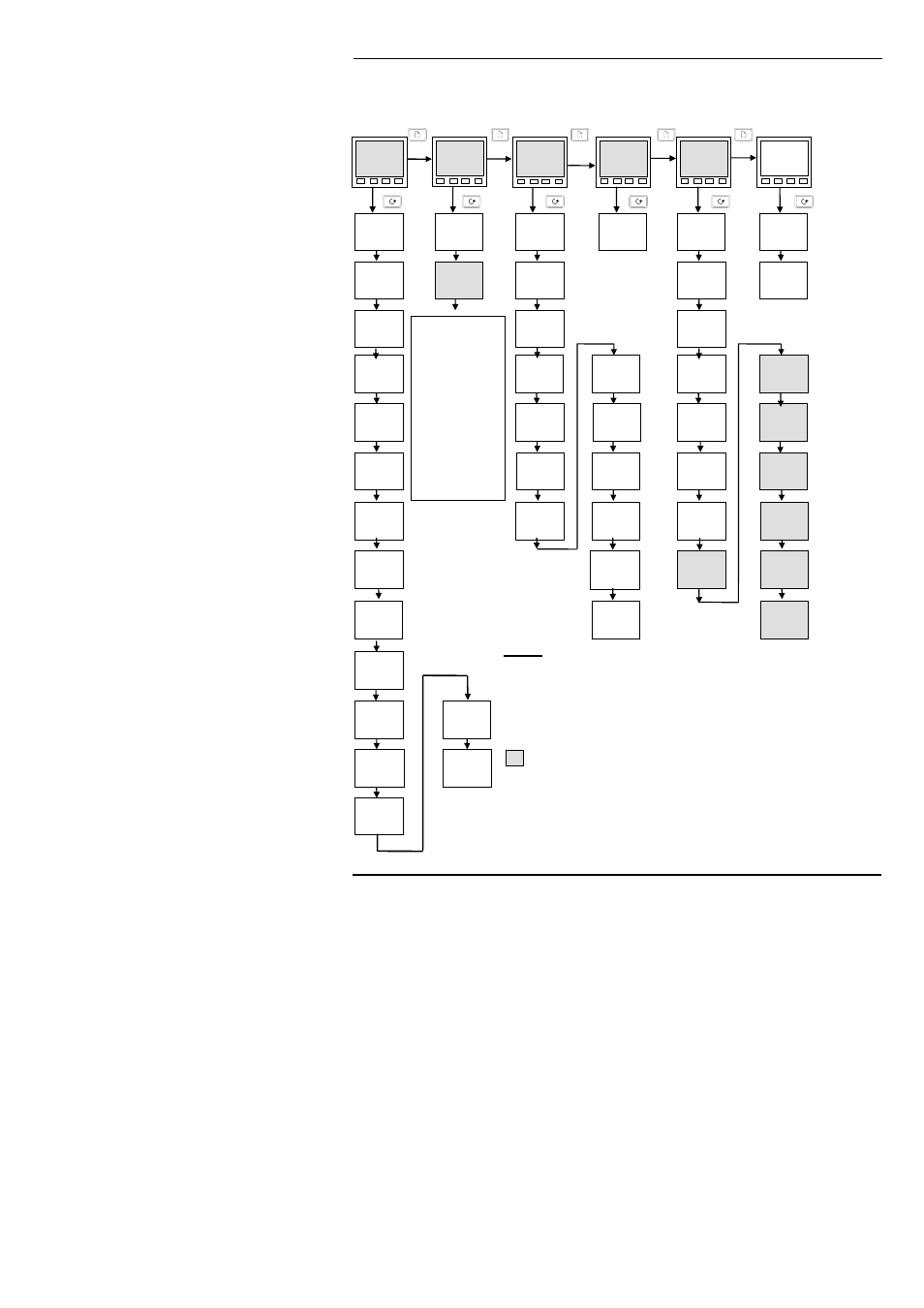
NAVIGATION DIAGRAM (PART B)
Figure 2-6b Navigation diagram (Part B)
SP
LiSt
iP
LiSt
oP
LiSt
cmS
LiSt
inFo
LiSt
Notes:
1. These lists are present only in controllers with the programming
feature.
2. The last three characters depend upon the type of alarm
configured.
3. This list is only present in motorised valve controllers.
4. Absolute setpoint limits are set in configuration, see Chapter 6.
The shaded boxes are normally hidden in Operator level. To
see all the available parameters you must select Full level.
See Chapter 3, Access Levels.
ACCS
LiSt
Goto
OPEr
codE
PASS
Setpoint
List
Input
List
Output
List
Comms
List
Information
List
Access
List
L-r
Loc
SSEL
SP 1
SP 1
20.0
rm.SP
0.0
SP 2
0.0
rmt.t
0.0
rat
Off
Hb.ty
Lo
Hb
10
OP.Hi
100.0
OP.Lo
0.0
OPrr
OFF
CYC.H
20.0
ont.H
Auto
Addr
1
LoG.H
100.0
LoG.L
0.0
LoG.A
50.0
LoG.t
1000
rES.L
no
LoG.v
0.0
mCt
0
hYS.H
1.0
FiLt
Off
SP L
4
0.0
SP H
4
100.0
SP2.H
4
100.0
SP2.L
4
0.0
SPrr
OFF
di SP
Std
P OP
19
I OP
10
d OP
1
FF.OP
0
w.OP
0.0
hYS.C
1.0
HC.db
0.0
CYC.C
5 0
ont.C
Auto
FOP
0.0
CAL
FACt
Sb.OP
100.0
The parameters
that follow
depend upon
the controller
configuration.
Refer to the
parameter table.
(over Page)
They cover: user
calibration.
Loc.t
0
VO
0
End.P
0.0
.