Thermcraft XST-3-0-36-3V User Manual
Page 243
Installation and Operation Handbook
Configuration
2416 Controller
6-13
Name
Description
Values
Meaning
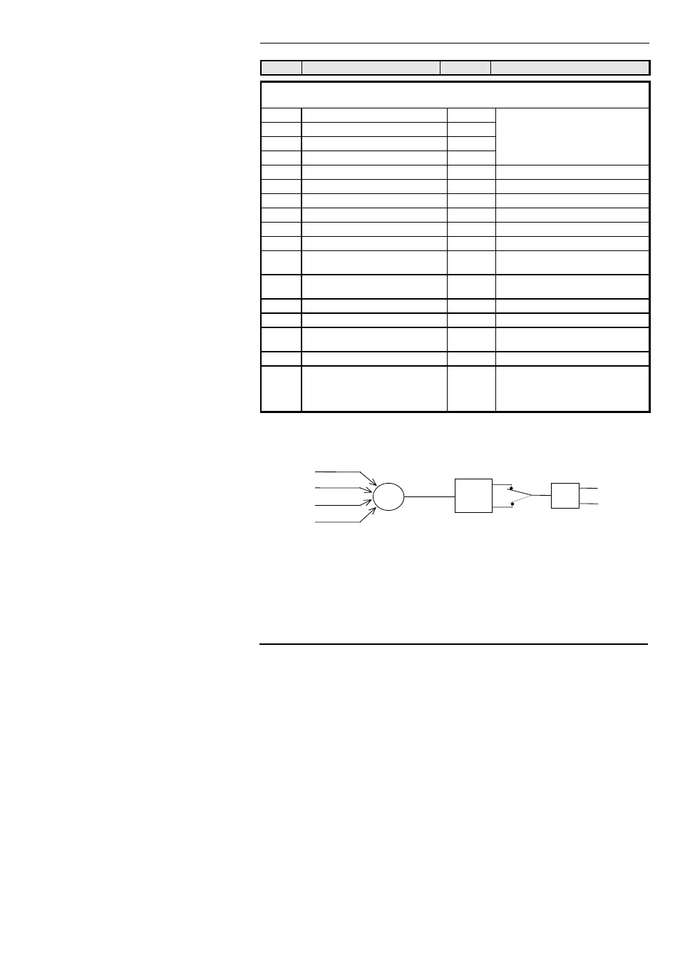
The following digital events appear after ‘
SEnS’. Any one, or more, of the events can be
combined on to the output (see Fig. 6-2) by selecting ‘
YES’ in the lower readout.
1 - - -
Alarm 1 active
YES / no (- - -) = alarm type (e.g. FSL).
2 - - -
Alarm 2 active
YES / no If an alarm has not been configured
3 - - -
Alarm 3 active
YES / no in ‘AL ConF’ list, then display will
4 - - -
Alarm 4 active
YES / no differ:- e.g. Alarm 1 = ‘AL 1’.
mAn
* Controller in manual mode
YES / no
Sbr
* Sensor break
YES / no
SPAn
* PV out of range
YES / no
Lbr
* Loop break
YES / no
Ld.F
* Load failure alarm
YES / no
tunE
* Tuning in progress
YES / no
dc.F
* Voltage output open circuit, or
mA output open circuit
YES / no
rmt.F
* PDS module connection or
remote input open circuit
YES / no
iP1.F * Input 1 fail (not usable on 2416) YES/no
nw.AL
* New Alarm has occurred
YES / no
End
* End of setpoint rate limit, or end
of program
YES / no
SYnc
* Program Synchronisation active
YES / no (Not available in 2416 - set to ‘no’)
PrG.n
* Programmer event output
active, where ‘n’ = event number
from 1 to 8. (Not available with
8-segment programmer.)
YES / no
* These alarms are always non-latching. Process alarms 1, 2, 3 and 4 are configurable as
alarm latching or non-latching, see the ‘
AL’ List
Figure 6-2 Combining several digital events on to one output
dIG
SEnS
nor
inv
Output
Module
Digital
Events
OR