4 chapter 4 tuning – Thermcraft XST-3-0-36-3V User Manual
Page 207
Installation and Operation Handbook
Tuning
2416 Controller
4-1
4 Chapter 4 TUNING
Before tuning please read Chapter 2, Operation, to learn how to select and change a
parameter.
This chapter has five main topics:
• WHAT IS TUNING?
• AUTOMATIC
TUNING
• MANUAL
TUNING
• COMMISSIONING OF MOTORISED VALVE CONTROLLERS
• GAIN
SCHEDULING
4.1
WHAT IS TUNING?
In tuning, you match the characteristics of the controller to that of the process being
controlled in order to obtain good control. Good control means:
• Stable ‘straight-line’ control of the temperature at setpoint without fluctuation
• No overshoot, or undershoot, of the temperature setpoint
• Quick response to deviations from the setpoint caused by external disturbances, thereby
restoring the temperature rapidly to the setpoint value.
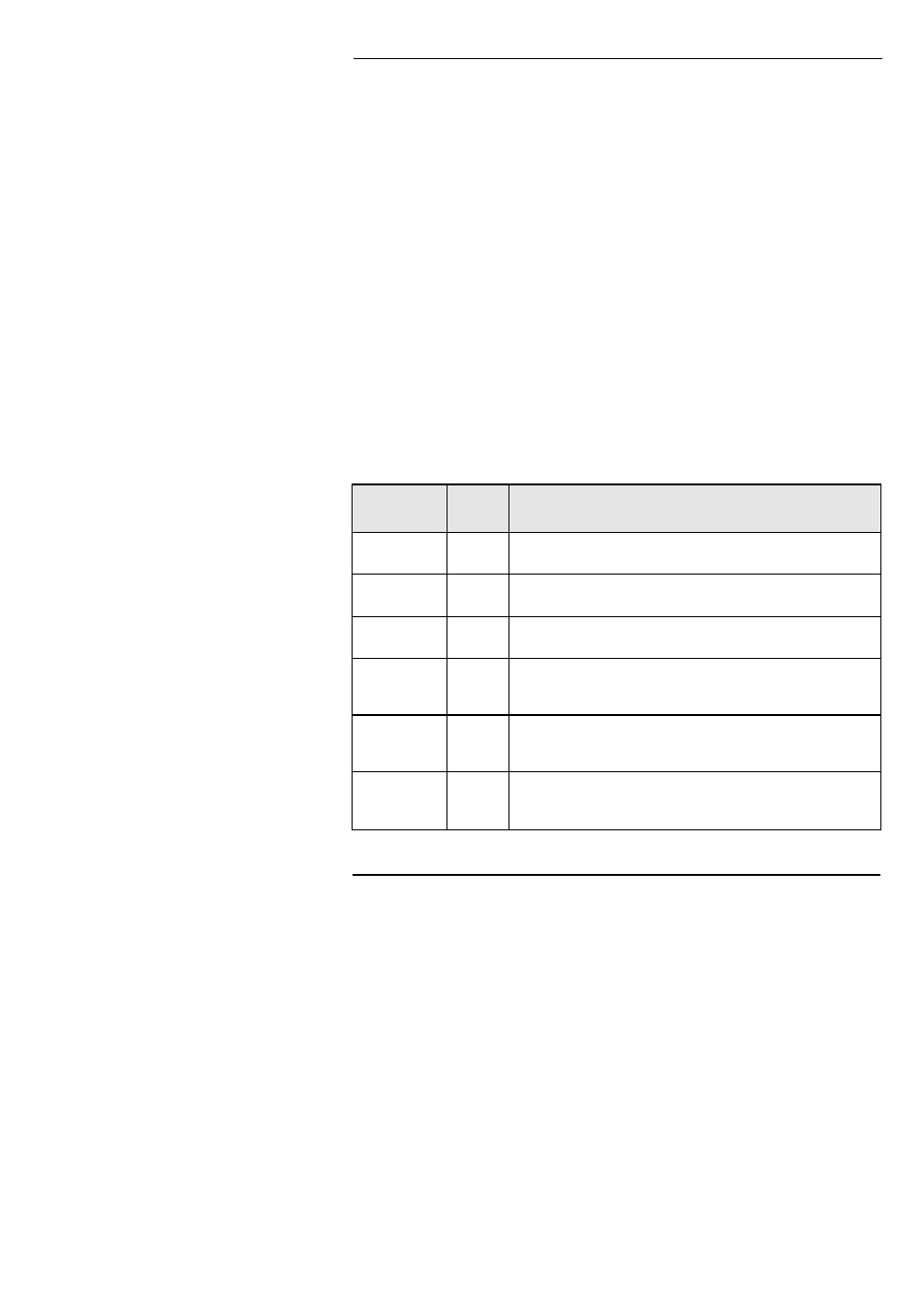
Tuning involves calculating and setting the value of the parameters listed in Table 4-1. These
parameters appear in the ‘
Pid’ list.
Parameter
Code
Meaning or Function
Proportional
band
Pb
The bandwidth, in display units, over which the output power is
proportioned between minimum and maximum.
Integral time
ti
Determines the time taken by the controller to remove steady-
state error signals.
Derivative
time
td
Determines how strongly the controller will react to the rate-of-
change of the measured value.
High Cutback
Hcb
The number of display units, above setpoint, at which the
controller will increase the output power, in order to prevent
undershoot on cool down.
Low cutback
Lcb
The number of display units, below setpoint, at which the
controller will cutback the output power, in order to prevent
overshoot on heat up.
Relative cool
gain
rEL
Only present if cooling has been configured and a module is
fitted. Sets the cooling proportional band, which equals the
Pb
value divided by the
rEL value.
Table 4-1 Tuning parameters