1 mechanical installation – Thermcraft XST-3-0-36-3V User Manual
Page 174
Installation
Installation and Operation Handbook
1-2
2416 Controller
WARNING
You must ensure that the controller is correctly configured for your application.
Incorrect configuration could result in damage to the process being controlled, and/or
personal injury. It is your responsibility as the installer to ensure that the configuration
is correct. The controller may either have been configured when ordered, or may need
configuring now. See Chapter 6, Configuration.
1.1 MECHANICAL
INSTALLATION
1.1.1 Controller
labels
The labels on the sides of the controller identify the ordering code, the serial number, and the
wiring connections.
Appendix A, Understanding the Ordering Code explains the hardware and software
configuration of your particular controller.
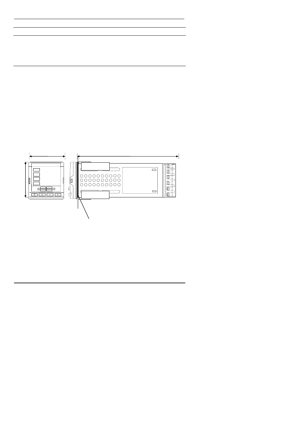
1.1.2
Outline dimensions
AUTO
RUN
HOLD
2416
MAN
OP1
OP2
SP2
REM
Figure 1-2 Outline dimensions
The electronic assembly of the controller plugs into a rigid plastic sleeve, which in turn fits
into the standard DIN size panel cut-out shown in Figure 1-3.
48mm
150mm
1.89in 5.91in
48mm
1.89in
IP65, NEMA 4X sealing gasket
OP1
OP2
SP2
REM
2416
200.0
200.0