Thermcraft XST-3-0-36-3V User Manual
Page 151
Installation and Operation Handbook Load Current Monitoring and Diagnostics
2408 and 2404 Controller D-5
How Heater Alarms Are Displayed
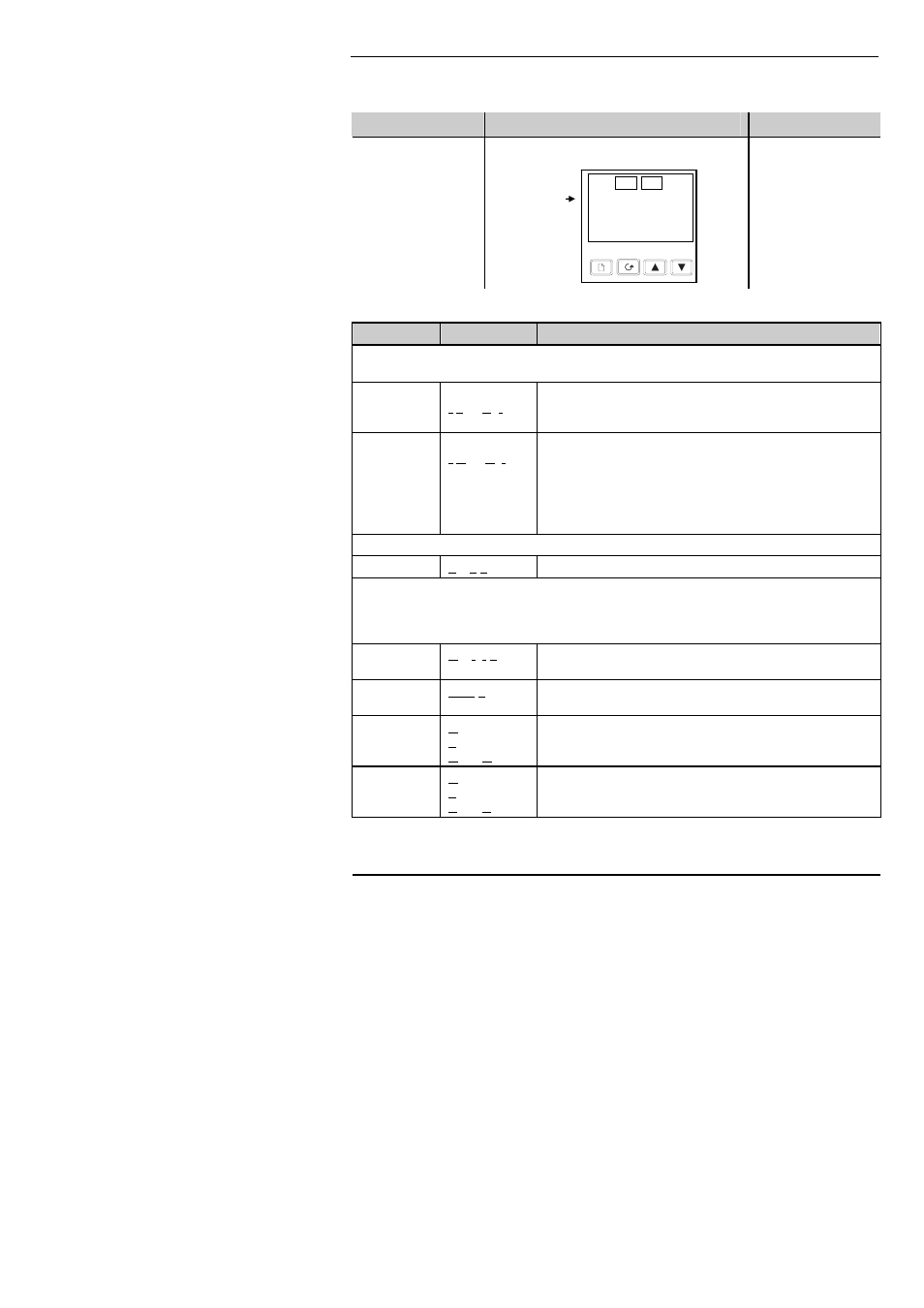
Do This
This Is The Display You Should See
Additional Notes
If an alarm is
present it will flash a
four character
mnemonic in the
lower display
If more than one
alarm is active, the
display will alternate
between the alarm
messages and the
default parameter in
the lower display
The Alarm Messages are:-
Mnemonic
Meaning
Description
The following two messages are alarms which are produced as a result of failure within the
process. In place of dashes the alarm number will appear i.e
1, 2, 3, or 4
-LCr
Alarm number
- Low Current
Used for partial load failure detection. To avoid nuisance
tripping due to supply voltage variations set to a value at
least 15% below the minimum normal operating current
-HCr
Alarm number
- High Current
Used for load overcurrent protection. To avoid nuisance
tripping due to supply voltage variations set to a value at
least 15% above the maximum normal operating current.
Note: This alarm is not intended to provide
instantaneous safety protection from short circuit fault
conditions
The following message is a diagnostic alarm which appears for mode 1 operation only.
LdF
Load Fail
This includes failure of the heater circuit or the SSR
The following four messages are diagnostic alarms produced as a result of failure within the
equipment or wiring connections. They appear for modes 2 and 5 operation only. They may
be enabled using the
diAG parameter in the AL LiSt, see ‘SHORT CIRCUIT SSR
ALARM AND HEATER FAIL ALARM’
Htr.F
Heater Fail
No current is being drawn while the controller output
demand signal is on
SSr.F
SSR Fail
The load is continuously on while the controller output
demand signal is off
Ct.OP
Current
Transformer
Open Circuit
Indicates that the PDS input is open circuit.
Mode 5 only
Ct.Sh
Current
Transformer
Short Circuit
Indicates that the PDS input is short circuit
Mode 5 only
Actual
Temperature
(PV)
HOME Display
20.0
1LCr
OP1
OP2