Parallel connector, Ps/2-compatible keyboard and mouse connectors, Table b – Dell PowerEdge SC 420 User Manual
Page 7: Defines the pin assignments for the connector
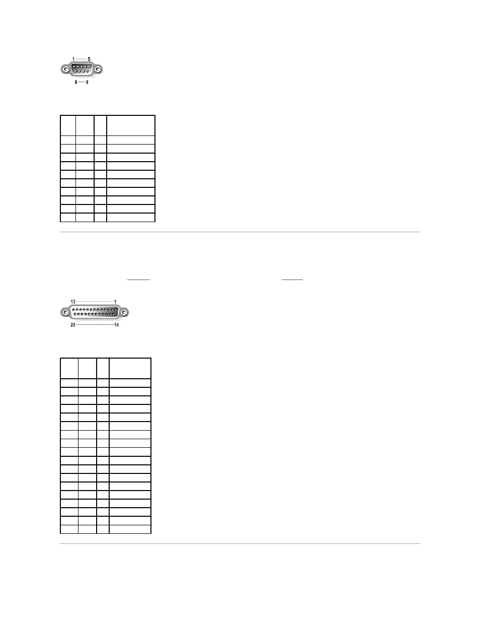
Table B-1. Serial Connector Pin Assignments
Parallel Connector
The integrated parallel connector, intended primarily for use by printers that require data in parallel format, uses a 25-pin D-subminiature connector on the
system's back panel. The default designation of the system's parallel connector is LPT1. If you add an expansion card containing a parallel connector
configured as LPT1 (IRQ7, I/O address 378h), use the System Setup program to remap the integrated parallel connector. See "Using the System Setup
Program" in the User's Guide.
illustrates the pin numbers for the parallel connector and
defines the pin assignments for the connector.
Figure B-3. Parallel Connector Pin Numbers
Table B-2. Parallel Connector Pin Assignments
PS/2-Compatible Keyboard and Mouse Connectors
Pin
Signal
I/O
Definition
1
DCD
I
Data carrier detect
2
SIN
I
Serial input
3
SOUT
O
Serial output
4
DTR
O
Data terminal ready
5
GND
N/A Signal ground
6
DSR
I
Data set ready
7
RTS
O
Request to send
8
CTS
I
Clear to send
9
RI
I
Ring indicator
Shell N/A
N/A Chassis ground
Pin
Signal
I/O
Definition
1
STB#
I/O Strobe
2
PD0
I/O Printer data bit 0
3
PD1
I/O Printer data bit 1
4
PD2
I/O Printer data bit 2
5
PD3
I/O Printer data bit 3
6
PD4
I/O Printer data bit 4
7
PD5
I/O Printer data bit 5
8
PD6
I/O Printer data bit 6
9
PD7
I/O Printer data bit 7
10
ACK#
I
Acknowledge
11
BUSY
I
Busy
12
P E
I
Paper end
13
SLCT
I
Select
14
AFD#
O
Automatic feed
15
ERR#
I
Error
16
INIT# O
Initialize printer
17
SLIN# O
Select in
18–25 GND
N/A Ground