Windows, Only) – Dell PowerEdge SC 420 User Manual
Page 49
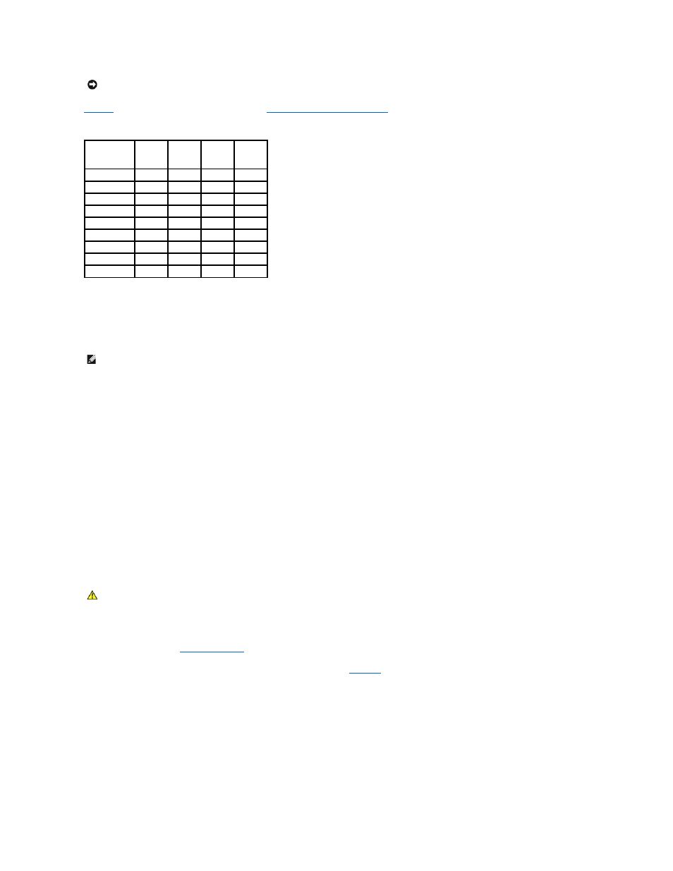
illustrates sample memory configurations. See "
Memory Module Installation Guidelines
" for detailed information.
Table 6-1. Sample Memory Configurations
Addressing Memory With 4-GB Configurations (Microsoft
®
Windows
®
Only)
Your system supports a maximum of 4 GB of memory using four 1-GB memory modules. Current operating systems can use a maximum of 4 GB of address
space; however, the amount of memory available to the operating system is slightly less than 4 GB.
Certain components within the system require address space in the 4-GB range. Any address space reserved for these components cannot be used by system
memory.
The following components require address space:
l
System ROM
l
Advanced Programmable Interrupt Controllers (APIC)
l
Integrated PCI devices (such as NICs) and SCSI controllers
l
PCI expansion cards
At start-up, the BIOS identifies the components that require address space. The BIOS dynamically calculates the amount of reserved address space required.
The BIOS then subtracts the reserved address space from 4 GB to determine the amount of usable space.
l
If the total installed system memory is less than the usable space, all installed system memory is available for use only by the operating system.
l
If the total installed system memory is equal to or greater than the usable address space, a small portion of installed memory is available for use by the
operating system.
Installing a Memory Module
1.
Turn off the system and attached peripherals, and disconnect the system from the electrical outlet.
2.
Open the system. See "
Opening the System
" in "Troubleshooting Your System."
3.
Press on the securing clip at each end of the memory module connector. See
.
4.
Align the memory module's edge connector with the alignment key in the connector.
The memory module connector has an alignment key that allows the memory module to be installed in the connector in only one way.
5.
Insert the module into the connector, and carefully press each end of the module into place.
Figure 6-3. Installing a Memory Module
NOTICE:
If you remove your original memory modules from the system during a memory upgrade, keep them separate from any new memory modules
that you may have, even if you purchased the new memory modules from Dell. Use only unregistered or unbuffered ECC DDR II memory modules.
Total Memory
DIMM_1
DIMM_2
DIMM_3
DIMM_4
256 MB
256 MB
none
none
none
512 MB
256 MB
256 MB
none
none
1 GB
256 MB
256 MB
256 MB
256 MB
1 GB
512 MB
512 MB
none
none
1 GB
1 GB
none
none
none
2 GB
512 MB
512 MB
512 MB
512 MB
2 GB
1 GB
1 GB
none
none
3 GB
1 GB
1 GB
512 MB
512 MB
4 GB
1 GB
1 GB
1 GB
1 GB
NOTE:
Depending on the type of PCI/PCIe expansion cards that are installed in your system, your system may only support a maximum of 3.4 GB of
memory or less.
CAUTION:
See your Product Information Guide for complete information about safety precautions, working inside the computer, and protecting
against electrostatic discharge.