System board connectors, Table a – Dell PowerEdge SC 420 User Manual
Page 3
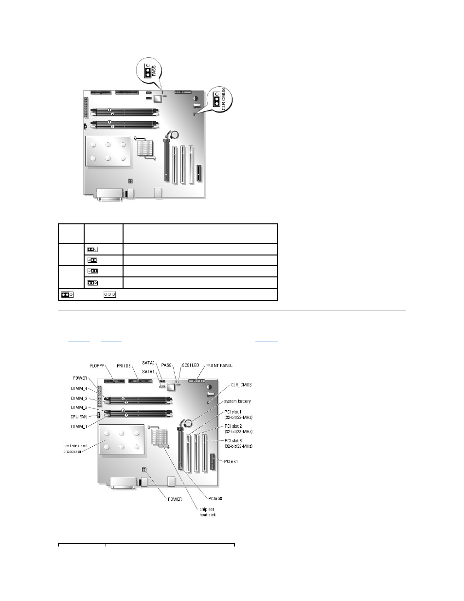
Table A-1. System Board Jumper Settings
System Board Connectors
for the location and description of system board connectors.
also indicates expansion slots and bus operating speeds.
Figure A-3. System Board Connectors
Table A-2. System Board Connectors
Jumper
Setting
Description
PASS
(default)
The password feature is enabled.
The password feature is disabled.
CLR CMOS
(default)
The configuration settings in NVRAM are retained at system boot.
The configuration settings in NVRAM are cleared at next system boot.
jumpered
unjumpered
See also other documents in the category Dell Computer hardware:
- PowerEdge RAID Controller H700 (56 pages)
- PowerEdge RAID Controller H700 (200 pages)
- PowerEdge RAID Controller H700 (178 pages)
- PowerVault TL2000 (1 page)
- PowerVault 110T DLT VS80 (Tape Drive) (49 pages)
- PowerVault TL2000 (22 pages)
- PowerVault TL4000 (306 pages)
- PowerVault TL2000 (2 pages)
- PowerVault TL4000 (2 pages)
- PowerVault TL2000 (176 pages)
- PowerVault TL2000 (16 pages)
- PowerVault TL2000 (3 pages)
- PowerVault TL2000 (116 pages)
- PowerVault 130T DLT (Tape Library) (49 pages)
- PowerEdge 800 (82 pages)
- PowerEdge 800 (2 pages)
- PowerEdge 800 (27 pages)
- PowerEdge 800 (28 pages)
- PowerEdge 800 (58 pages)
- PowerEdge 800 (87 pages)
- PowerEdge 800 (24 pages)
- PowerEdge 6400 (86 pages)
- PowerVault 124T (57 pages)
- PowerVault 110T LTO (Tape Drive) (28 pages)
- PowerVault 124T (55 pages)
- PowerVault 124T (73 pages)
- PowerVault 124T (65 pages)
- PowerVault 124T (4 pages)
- PowerVault 124T (79 pages)
- PowerVault 124T (2 pages)
- PowerVault 124T (64 pages)
- PowerVault 124T (56 pages)
- PowerVault 124T (66 pages)
- PowerVault TL4000 (116 pages)
- PowerVault TL4000 (1 page)
- PowerVault TL4000 (66 pages)
- PowerVault TL4000 (22 pages)
- PowerVault TL4000 (3 pages)
- PowerVault TL4000 (176 pages)
- PowerVault TL4000 (2 pages)
- PowerVault TL4000 (16 pages)
- PowerEdge RAID Controller 6i (120 pages)
- PowerEdge RAID Controller 6i (156 pages)
- PowerVault 715N (Rackmount NAS Appliance) (56 pages)
- PowerVault 715N (Rackmount NAS Appliance) (86 pages)