System board, Installing the chassis intrusion switch, Removing the system board – Dell PowerEdge SC 420 User Manual
Page 14
5.
Remove the switch and its attached cable from the system.
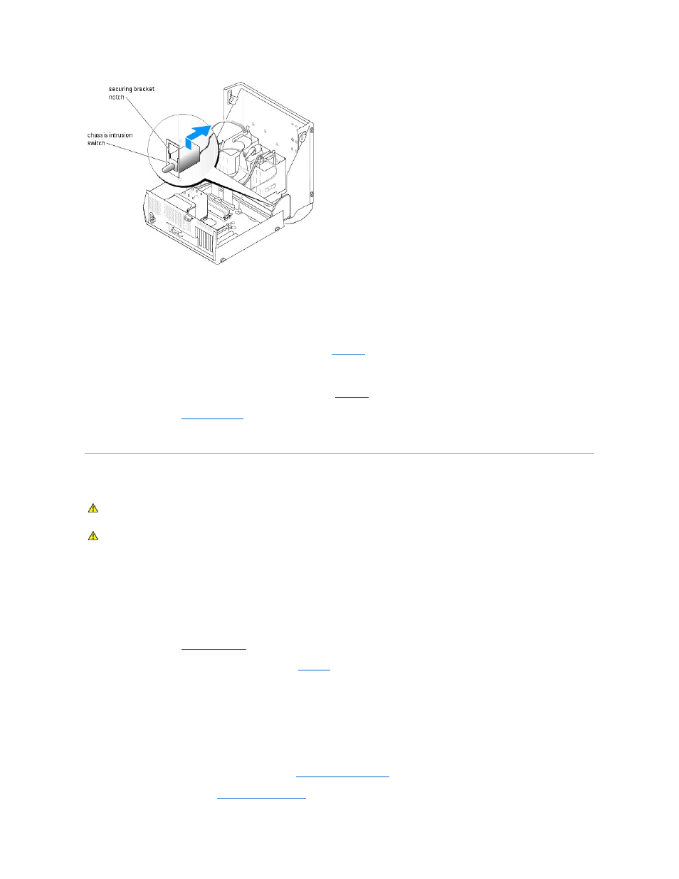
Installing the Chassis Intrusion Switch
1.
Align the chassis intrusion switch with the securing bracket notch. See
2.
Slide the switch into the securing bracket notch.
3.
Connect the switch cable to the switch connector on the I/O panel. See
4.
Close the system. See "
Closing the System
" in "Troubleshooting Your System."
5.
Reconnect the system to the electrical outlet, and turn on the system.
System Board
The system board and system board tray are removed and replaced as a single assembly.
Removing the System Board
1.
Turn off the system and attached peripherals, and disconnect the system from the electrical outlet.
2.
Open the system. See "
Opening the System
" in "Troubleshooting Your System."
3.
Disconnect the following cables from the system board. See
Figure A
-3
in "Jumpers and Connectors":
l
Two power-supply cables from the POWER connectors
l
If applicable, diskette data cable from the FLOPPY connector
l
I/O panel cable from the FRONT PANEL connector
l
5.25-inch device data cable from PRI IDE connector
l
Cooling fan from the CPU_FAN connector
l
If applicable, SATA hard-drive data cable(s) from SATA0 and SATA1 connector(s)
4.
Remove all expansion cards and any attached cables. See "
Removing an Expansion Card
" in "Installing System Components."
5.
Remove all memory modules. See "
Removing a Memory Module
" in "Installing System Components."
CAUTION:
See your Product Information Guide for complete information about safety precautions, working inside the computer, and protecting
against electrostatic discharge.
CAUTION:
The heat sink can get hot during operation. To avoid burns, ensure that the system has sufficient time to cool before removing the
system board.