Sas/sata backplane board connectors, Sideplane board connectors – Dell POWEREDGE R805 User Manual
Page 60
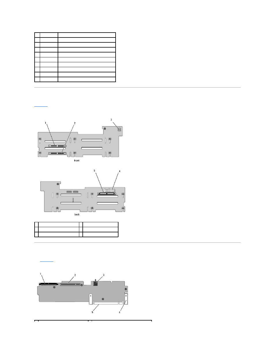
SAS/SATA Backplane Board Connectors
shows the location of the connectors on the SAS/SATA backplane board.
Figure 6-3. SAS/SATA Backplane Board Components
Sideplane Board Connectors
for the location and description of connectors on the sideplane board.
Figure 6-4. Sideplane Board Connectors
25 A1
First memory module slot (processor 1)
26 A2
Second memory module slot (processor 1)
27 A3
Third memory module slot (processor 1)
28 A4
Fourth memory module slot (processor 1)
29 A5
Fifth memory module slot (processor 1)
30 A6
Sixth memory module slot (processor 1)
31 A7
Seventh memory module slot (processor 1)
32 A8
Eighth memory module slot (processor 1)
33 FAN5
System cooling fan
34 FAN6
System cooling fan
1 drive 0 connector
2 drive 1 connector
3 optical drive power (CD_PWR) 4 backplane power (BKPLN)
5 SAS connector (SAS)
- Inspiron 530 (2 pages)
- OptiPlex 755 (248 pages)
- OptiPlex 755 (622 pages)
- OptiPlex 755 (528 pages)
- OptiPlex 755 (82 pages)
- OptiPlex 755 (45 pages)
- OptiPlex 760 (76 pages)
- OptiPlex 760 (203 pages)
- OptiPlex 745 (212 pages)
- OptiPlex 745 (360 pages)
- OptiPlex 745 (428 pages)
- OptiPlex 780 (73 pages)
- OptiPlex 780 (40 pages)
- OptiPlex 780 (14 pages)
- OptiPlex 780 (89 pages)
- OptiPlex 780 (10 pages)
- OptiPlex 780 (74 pages)
- OptiPlex 780 (80 pages)
- OptiPlex GX620 (221 pages)
- OptiPlex GX620 (294 pages)
- OptiPlex GX620 (338 pages)
- Inspiron 530 (226 pages)
- OptiPlex 960 (Late 2008) (16 pages)
- OptiPlex GX260 (100 pages)
- OptiPlex GX260 (235 pages)
- OptiPlex FX160 (Late 2008) (20 pages)
- OptiPlex FX160 (Late 2008) (132 pages)
- OptiPlex FX160 (20 pages)
- OptiPlex 210L (130 pages)
- OptiPlex 210L (128 pages)
- OptiPlex 210L (300 pages)
- OptiPlex 210L (258 pages)
- OptiPlex 210L (150 pages)
- OptiPlex 320 (266 pages)
- OptiPlex 320 (356 pages)
- OptiPlex 320 (44 pages)
- OptiPlex 320 (140 pages)
- OptiPlex 320 (132 pages)
- OptiPlex 320 (312 pages)
- OptiPlex GX240 (182 pages)
- OptiPlex GX240 (144 pages)
- OptiPlex GX240 (121 pages)
- OptiPlex GX240 (86 pages)
- OptiPlex GX240 (283 pages)
- OptiPlex GX240 (298 pages)