Lcd status messages, Table 1, Lists the nic indicator – Dell POWEREDGE R805 User Manual
Page 6
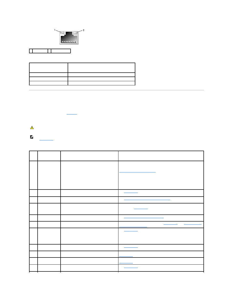
Table 1-5. NIC Indicator Codes
LCD Status Messages
The system's control panel LCD provides status messages to signify when the system is operating correctly or when the system needs attention.
The LCD lights blue to indicate a normal operating condition, and lights amber to indicate an error condition. The LCD scrolls a message that includes a status
code followed by descriptive text.
to events recorded in the System Event Log (SEL). For information on the SEL and configuring system management settings, see the systems management
software documentation.
Table 1-6. LCD Status Messages
1 link indicator 2 activity indicator
Indicator
Indicator Code
Link and activity indicators are off The NIC is not connected to the network.
Link indicator is green
The NIC is connected to a valid link partner on the network.
Activity indicator is amber blinking Network data is being sent or received.
CAUTION:
Many repairs may only be done by a certified service technician. You should only perform troubleshooting and simple repairs as
authorized in your product documentation, or as directed by the online or telephone service and support team. Damage due to servicing that is not
authorized by Dell is not covered by your warranty. Read and follow the safety instructions that came with the product.
NOTE:
If your system fails to boot, press the System ID button for at least five seconds until an error code appears on the LCD. Record the code, then
see
Getting Help
.
Code
Text
Causes
Corrective Actions
N/A
SYSTEM NAME
A 62-character string that can be defined by the user
in the System Setup program.
The SYSTEM NAME displays under the following
conditions:
l
The system is powered on.
l
The power is off and active errors are
displayed.
This message is for information only.
You can change the system ID and name in the System Setup program. See
Using the System Setup Program
.
E1000 FAILSAFE, Call
Support
Check the system event log for critical failure
events.
See
Getting Help
.
E1114 Temp Ambient
Ambient system temperature is out of acceptable
range.
See
Troubleshooting System Cooling Problems
.
E1118 CPU Temp
Interface
The BMC is unable to determine the CPU(s)
temperature status. Consequently, the BMC
increases the CPU fan speed to maximum
as a precautionary measure.
Turn off power to the system and restart the system. If the problem
persists, see
Getting Help
.
E1210 CMOS Batt
CMOS battery is missing, or the voltage is out of
acceptable range.
See
Troubleshooting the System Battery
.
E1211 ROMB Batt
RAID battery is either missing, bad, or unable to
recharge due to thermal issues.
Reseat the RAID battery connector. See
RAID Battery
, and
Troubleshooting
System Cooling Problems
.
E1214
E1216
E1217
## PwrGd
Specified voltage regulator has failed.
See
Getting Help
.
E1218 PCI Rsr 5V PwrGd
The 5V voltage regulator on the PCI riser has
failed.
See
Getting Help
.
E121A 8V PwrGd
8V voltage regulator has failed.
Recycle power to the system or clear the SEL. If the problem persists, see
Getting Help
.
E121D 1.2V VM Dual
PwrGd
1.2V voltage regulator for the VM dual signal has
failed.
Recycle power to the system or clear the SEL. If the problem persists, see
Getting Help
.
E1226 PCI Rsr 1.5V
PwrGd
The 1.5V voltage regulator on the PCI riser has
failed.
See
Getting Help
.