Expansion cards – Dell POWEREDGE R805 User Manual
Page 34
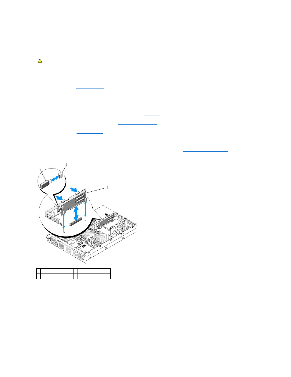
Installing the Optional Internal USB Memory Key
1.
Turn off the system, including any attached peripherals, and disconnect the system from its electrical outlet.
2.
3.
Locate the USB connector on expansion-card riser 2 (see
Figure 6
-4
).
If you have full-length expansion card in slot 3, you may have to remove the card to install the USB key. See
.
4.
Insert the USB memory key into the USB connector onto the board. See
.
5.
If applicable, install the expansion card in slot 3. See
.
6.
.
7.
Reconnect the system to power and restart the system.
8.
Enter the System Setup program and verify that the USB key has been detected by the system. See
Using the System Setup Program
.
Figure 3-13. Installing an Internal USB Key
Expansion Cards
The system supports up to four PCI Express (PCIe) expansion cards.
l
Expansion-card riser 1 provides two slots:
¡
Slot 1 is a full-length PCIe x8-lane expansion slot.
¡
Slot 2 is a half-length PCIe x4-lane expansion slot.
l
Expansion-card riser 2 provides two slots:
¡
Slot 3 is a full-length PCIe x8-lane expansion slot.
¡
Slot 4 is a half-length PCIe x8-lane expansion slot.
CAUTION:
Many repairs may only be done by a certified service technician. You should only perform troubleshooting and simple repairs as
authorized in your product documentation, or as directed by the online or telephone service and support team. Damage due to servicing that is not
authorized by Dell is not covered by your warranty. Read and follow the safety instructions that came with the product.
1 USB memory key
2 internal USB connector
3 expansion-card riser 2