Board tray riser release pin. see, Figure 3, Installing the system board – Dell POWEREDGE R805 User Manual
Page 57
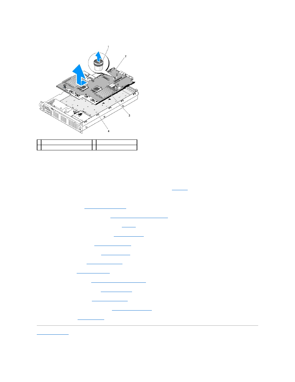
Figure 3-32. System Board Removal
Installing the System Board
1.
Lower the system-board tray until the tray sits flat on the bottom of the chassis.
2.
Align the back connectors on the system board with the cutouts in the back of the chassis, and ensure the system-board tray is square with the chassis
so that the securing tabs on the chassis fully insert into system- board securing slots. See
.
3.
Slide the system-board tray toward the back of the chassis until it locks into position.
4.
Replace the sideplane. See
Installing the Sideplane Board
5.
Replace the SAS controller daughter card. See
Installing a SAS Controller Daughter Card
.
6.
Reinstall the LOM NIC hardware key, if applicable. See
Figure 6
-2
for the TOE_KEY socket location.
7.
Replace the heatsinks and microprocessors. See
8.
Replace the memory modules. See
.
9.
If applicable, replace the RAC card. See
.
10.
Replace the fan bracket. See
11.
.
12.
Replace the cooling shroud. See
Installing the Processor Cooling Shroud
.
13.
Replace the expansion-card risers. See
.
14.
Replace the power supplies. See
15.
If applicable, replace any expansion cards. See
16.
.
Back to Contents Page
1 system-board tray riser release pin 2 system board
3 system-board tray
4 system-board securing tabs