Diskette drive, Interface cables, Drive cable configurations – Dell PowerVault DP100 User Manual
Page 37: Dc power cables, Removing a diskette drive, Installing a diskette drive
Interface Cables
Most interface connectors are keyed for correct insertion. Keying ensures that the pin-1 wire in the cable connects to pin 1 in the connectors on both ends.
When you disconnect an interface cable, take care to grasp the cable connector, rather than the cable itself, to avoid stress on the cable.
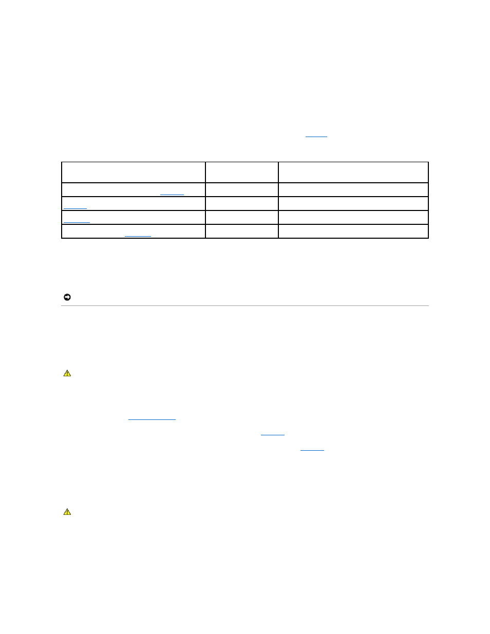
Drive Cable Configurations
shows the cable requirements for common
drive configurations.
Table 3-1. Drive Cable Configuration
DC Power Cables
Each drive must connect to a DC power cable from the system power supply. These power cables are used for the 3.5-inch diskette drive, 5.25-inch devices,
and hard drives.
Diskette Drive
Removing a Diskette Drive
1.
Turn off the system, including any attached peripherals, and disconnect the system from the electrical outlet.
2.
3.
Disconnect the power cable and the interface cable from the diskette drive. See
4.
Remove the two screws that secure the diskette drive in the externally accessible drive bay. See
5.
Slide the diskette drive forward out of the drive bay.
Installing a Diskette Drive
1.
Unpack the drive and prepare the drive for installation.
For instructions, see the documentation that accompanied the drive.
2.
Slide the diskette drive into the externally accessible drive bay.
Drives
Required Cable
Cable Connections
IDE optical drives, internal IDE and external SCSI tape
drives (with optional SCSI HBA card) (See
.)
80-pin IDE 2-drop cable or
external SCSI cable
IDE drive and primary IDE connector on system board or
external SCSI tape device (with option SCSI HBA card)
Up to four cabled SATA hard drives (non-hot-plug) (See
.)
7-pin SATA hard-drive cable
(one cable per drive)
SATA hard drives and SATA port connectors on the system
board, or via SAS controller card
Up to four cabled (non-hot-plug) SAS hard-drives (See
32-pin 1- to 4-drop SAS cable SAS hard drives connected to SAS controller card
Up to four SAS or SATA hard drives connected to the SAS
backplane (hot plug) (See
32-pin SAS backplane cable
SAS backplane connected to the SAS controller card
NOTICE:
To avoid electrical damage to internal system components, install a cover connector on any unused connectors on hard-drive power cables.
CAUTION:
Only trained service technicians are authorized to remove the system cover and access any of the components inside the system.
Before performing any procedure, see your Product Information Guide for complete information about safety precautions, working inside the
computer, and protecting against electrostatic discharge.