3 screw chart, Screw chart – Dell Latitude XT2 XFR (Late 2009) User Manual
Page 25
Dell
™
Latitude™ XT2 XFR Service Manual
Page 25 of 94
Version A00-01
After you complete any replacement procedure, ensure you connect any external devices, cards, and
cables before turning on your computer.
CAUTION:
To avoid damage to the XT2 XFR, use only the battery designed for this
particular Dell computer. Do not use batteries designed for other Dell computers.
1. Connect any external devices, such as a port replicator, battery slice, or media base, and
replace any cards, such as an ExpressCard.
2. Connect any telephone or network cables to your XT2 XFR.
CAUTION:
To connect a network cable, first plug the cable into the network device and
then plug it into the computer.
4. Connect your XT2 XFR and all attached devices to their electrical outlets.
5. Turn on your XT2 XFR.
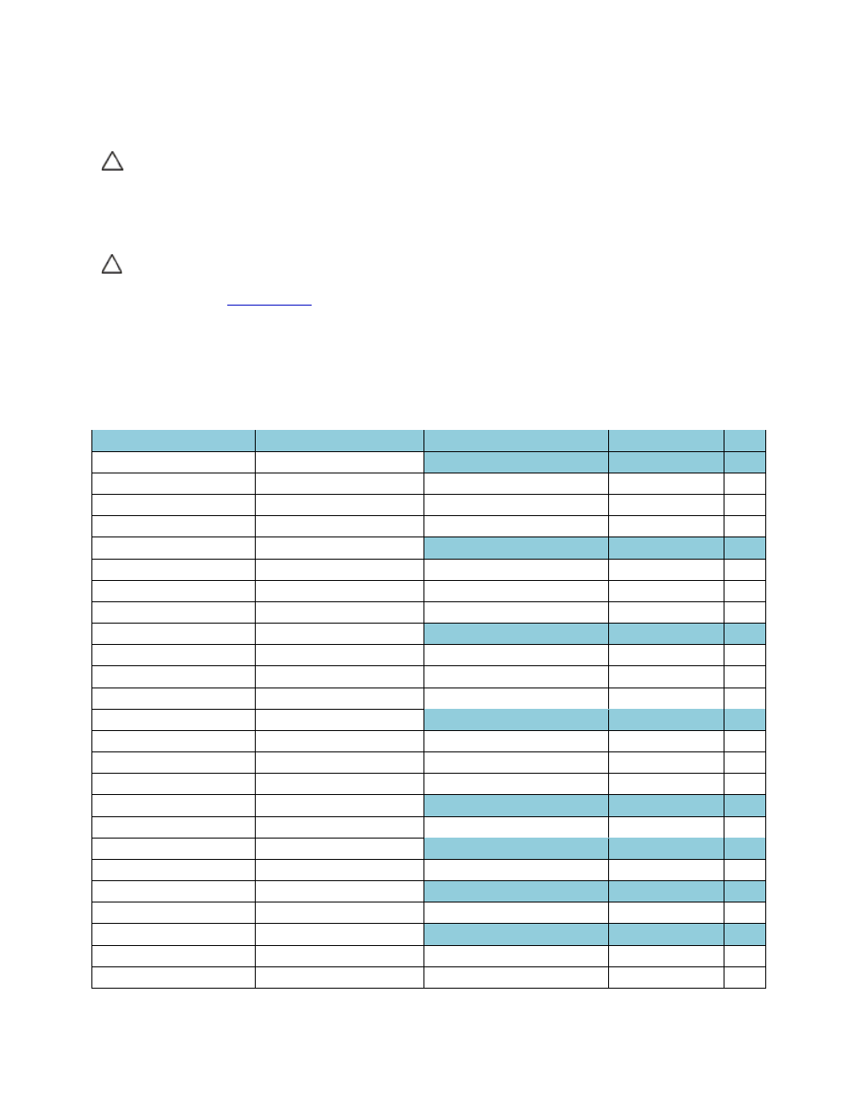
3 Screw Chart
Chassis
Location
Screw
Part #
Qty
1 USB/1394 DOOR
hinge assy screw-M3 x 3
21106-03
2
Latch screw-M1.2
40621
1
door to chassis mouting screw
21106-00
4
2 IO/AUDIO DOOR
hinge assy screw-M3 x 3
21106-03
3
Latch screw-M1.2
40621
1
door to chassis mouting screw
21106-00
6
3 IO/VGA DOOR
hinge assy screw-M3 x 3
21106-03
2
Latch screw-M1.2
40621
1
door to chassis mouting screw
21106-00
4
4 POWER DOOR
hinge assy screw-M3 x 3
21106-03
1
Latch screw-M1.2
40621
1
door to chassis mouting screw
21106-00
2
5 RF PASS THRU
M2 x 3
21106-00
2
6 STYLUS BAY
Self tapping screw
40426
1
7 SNIFFER ASSEMBLY
M2 x 3
21106-00
2
8 SYSTEM BOARD
M2.5 x 5
21106-01
1
M2.5 x 8
21106-02
1