Step 10 install an operating system – Dell PERC 4/DC User Manual
Page 60
The BIOS Configuration Utility prompt times out after several seconds.
The host controller number, firmware version, and cache SDRAM size display in the second portion of the BIOS message. The numbering of the controllers
follows the PCI slot scanning order used by the host motherboard.
Light-emitting Diode (LED) Description
When you start the system, the boot block and firmware perform a number of steps that load the operating system and allow the system to function properly.
The boot block contains the operating system loader and other basic information needed during startup.
As the system boots, the LEDs indicate the status of the boot block and firmware initialization and whether the system performed the steps correctly. If there
is an error during startup, you can use the LED display to identify it.
displays the LEDs and execution states for the boot block.
displays the LEDs and execution states during firmware initialization. The LEDs
display in hexadecimal format so that you can determine the number and the corresponding execution state from the LEDs that display.
Table 3-4. Boot Block States
Table 3-5. Firmware Initialization States
Step 9 Run the BIOS Configuration Utility or Dell Manager
Press
functions, such as configuring arrays and logical drives.
See
BIOS Configuration Utility and Dell Manager
for additional information about running the BIOS Configuration Utility and Dell Manager.
Step 10 Install an Operating System
Install one of the following operating systems: Microsoft® Windows NT®, Windows® 2000, Windows 2003, Novell® NetWare®, and Red Hat Linux.
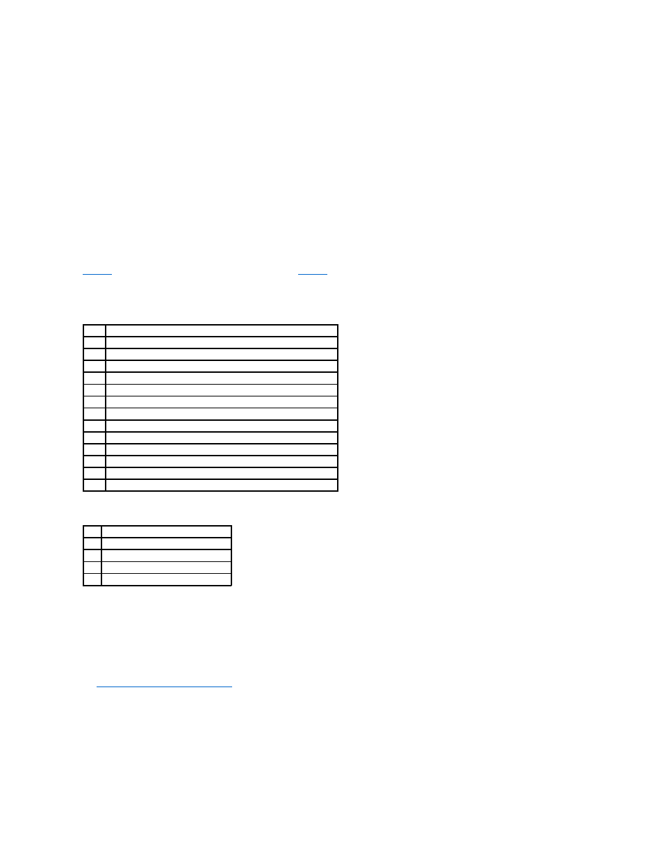
LED
Execution State
0x01 Setup 8-bit Bus for access to Flash and 8 Bit devices successful
0x03 Serial port initialization successful
0x04 Spd (cache memory) read successful
0x05 SDRAM refresh initialization sequence successful
0x07 Start ECC initialization and memory scrub
0x08 End ECC initialization and memory scrub
0x10 SDRAM is present and properly configured. About to program ATU.
0x11 CRC check on the firmware image successful. Continue to load firmware.
0x12 Initialization of SCSI chips successful.
0x13 BIOS protocols ports initialized. About to load firmware.
0x17 Firmware is either corrupt or BIOS disabled. Firmware was not loaded.
0x19 Error ATU ID programmed.
0x55 System Halt: Battery Backup Failure
LED Execution State
0x1 Begin Hardware Initialization
0x3 Begin Initialize ATU
0x7 Begin Initialize Debug Console
0xF Set if Serial Loopback Test is successful