Step 2 power down the system, Step 3 set jumpers – Dell PERC 4/DC User Manual
Page 55
Unpack and remove the controller and inspect it for damage. If the controller appears damaged, or if any items listed below are missing, contact your Dell
support representative. The RAID controller is shipped with:
l
The PERC 4 RAID Controller User's Guide (on CD)
l
The CERC and PERC RAID Controllers Operating System Driver Installation Guide (on CD)
l
A license agreement
Step 2 Power Down the System
Perform the following steps to power down the system:
1.
Turn off the system.
2.
Remove the AC power cord.
3.
Disconnect the system from any networks before installing the controller.
4.
Remove the system's cover.
Please consult the system documentation for instructions.
Step 3 Set Jumpers
Make sure the jumper settings on the RAID controller are correct. Following are diagrams of the controllers showing their jumpers and connectors, and tables
describing them. Select your controller from the ones shown on the following pages.
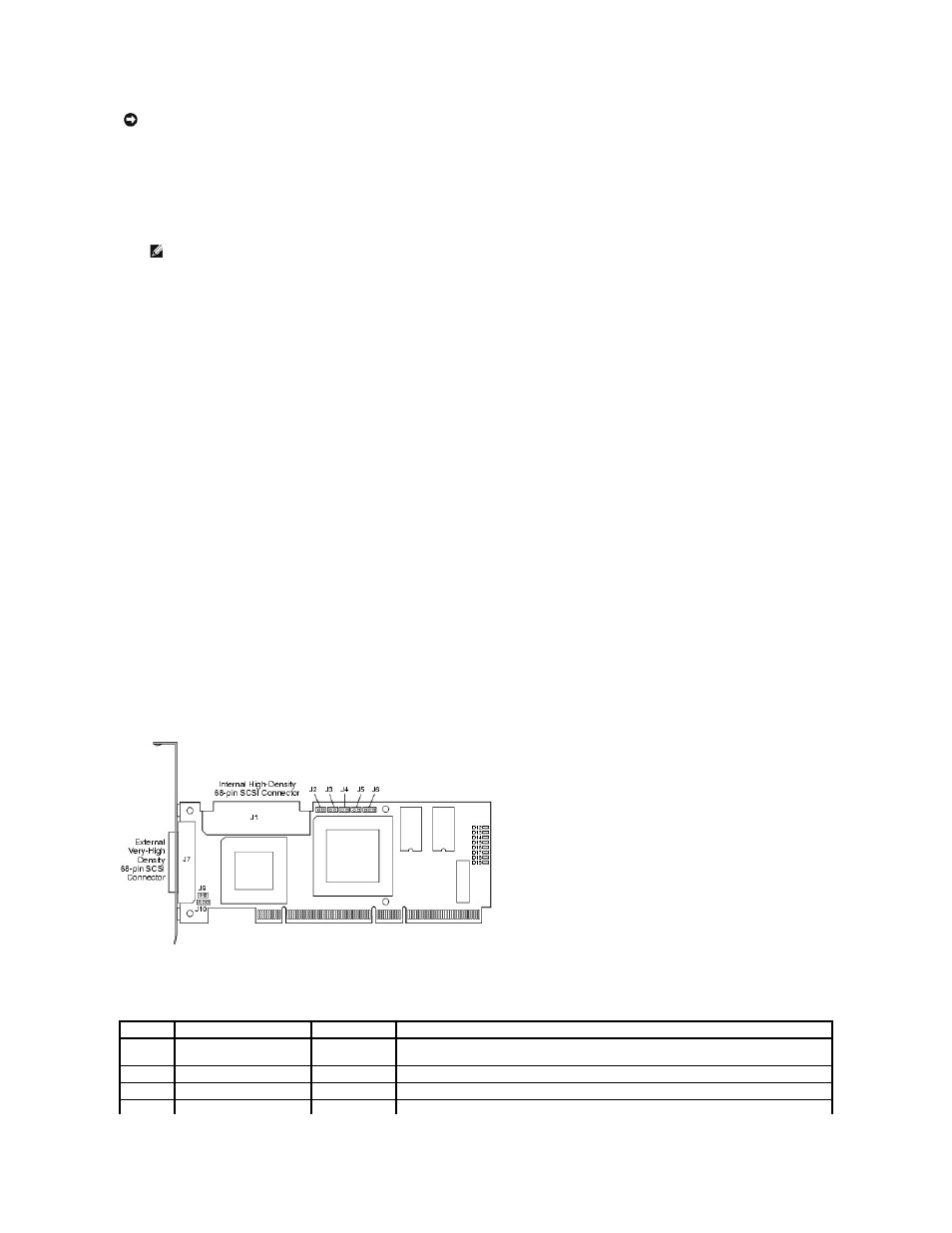
PERC 4/SC Jumpers and Connectors
Figure 3-1. PERC 4/SC Controller Layout
Table 3-1. PERC 4/SC Jumper and Connector Descriptions
NOTICE:
See the safety instructions in your system documentation for information about protecting against electrostatic discharge.
NOTE:
You can order a hard copy of the documentation for the controller.
Connector Description
Type
Setting
J1
Internal SCSI connector
68-pin
connector
Internal high-density SCSI bus connector.
Connection is optional.
J2
NVRAM Clear
2-pin header
To CLEAR configuration data, install a jumper.
J3
Serial EPROM
2-pin header
To CLEAR configuration data, install a jumper.
J4
Onboard BIOS Enable
2-pin header
No jumper = Enabled (Default is Enabled)