Dell PERC 4/DC User Manual
Page 11
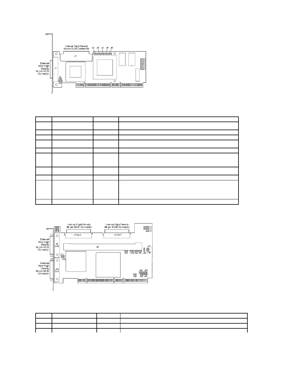
Table 3-1. PERC 4/SC Jumper and Connector Descriptions
Figure 3-2. PERC 4/DC Controller Layout
Table 3-2. PERC 4/DC Jumper and Connector Descriptions
Connector Description
Type
Setting
J1
Internal SCSI connector
68-pin connector Internal high-density SCSI bus connector.
Connection is optional.
J2
NVRAM Clear
2-pin header
To CLEAR configuration data, install a jumper.
J3
Serial EPROM
2-pin header
To CLEAR configuration data, install a jumper.
J4
Onboard BIOS Enable
2-pin header
No jumper = Enabled (Default is Enabled)
With jumper in = Disabled
J5
SCSI Activity
2-pin header
Connector for enclosure LED to indicate data transfers. Connection is optional.
J6
Serial Port
3-pin header
Connector is for diagnostic purposes.
Pin-1 RXD (Receive Data)
Pin-2 TXD (Transmit Data)
Pin-3 GND (Ground)
J7
External SCSI connector
68-pin connector External very-high density SCSI bus connector.
Connection is optional.
J9
SCSI bus TERMPWR Enable
2-pin header
Install jumper to enable onboard termination power. Default is installed.
J10
SCSI bus Termination Enable 3-pin header
Jumper pins 1-2 to enable software control of SCSI termination through drive detection.
Jumper pins 2-3 to disable onboard SCSI termination.
No jumper installed enables onboard SCSI termination. This is the default.
D12 - D19 LEDs
Indicate problems with the card.
Connector Description
Type
Settings
J1
I2C Header
4-pin header
Reserved.
J2
SCSI Activity LED
4-pin header
Connector for LED on enclosure to indicate data transfers. Optional.
J3
Write Pending Indicator
2-pin header
Connector for enclosure LED to indicate when data in the cache has yet to be written to the