Dell PERC 4/DC User Manual
Page 56
PERC 4/DC Jumpers and Connectors
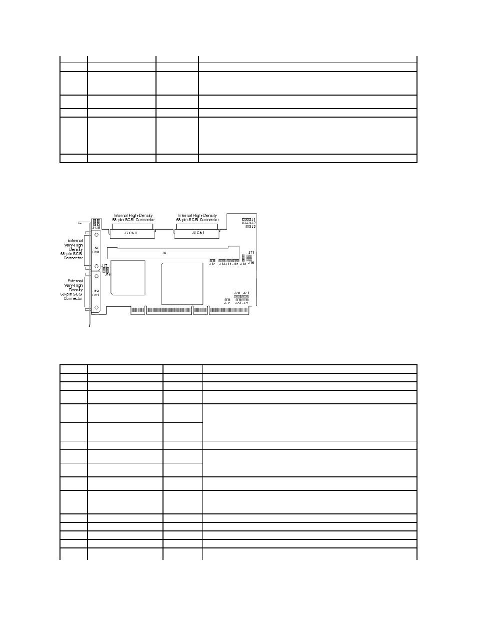
Figure 3-2. PERC 4/DC Controller Layout
Table 3-2. PERC 4/DC Jumper and Connector Descriptions
With jumper in = Disabled
J5
SCSI Activity
2-pin header
Connector for enclosure LED to indicate data transfers. Connection is optional.
J6
Serial Port
3-pin header
Connector is for diagnostic purposes.
Pin-1 RXD (Receive Data)
Pin-2 TXD (Transmit Data)
Pin-3 GND (Ground)
J7
External SCSI connector
68-pin
connector
External very-high density SCSI bus connector.
Connection is optional.
J9
SCSI bus TERMPWR Enable
2-pin header
Install jumper to enable onboard termination power. Default is installed.
J10
SCSI bus Termination
Enable
3-pin header
Jumper pins 1-2 to enable software control of SCSI termination through drive detection.
Jumper pins 2-3 to disable onboard SCSI termination.
Having no jumper installed enables onboard SCSI termination. The default is no jumper
installed.
D12 - D19 LEDs
Indicate problems with the card.
Connector Description
Type
Settings
J1
I2C Header
4-pin header
Reserved.
J2
SCSI Activity LED
4-pin header
Connector for LED on enclosure to indicate data transfers. Optional.
J3
Write Pending Indicator
(Dirty Cache LED)
2-pin header
Connector for enclosure LED to indicate when data in the cache has yet to be written to the
device. Optional.
J4
SCSI Termination Enable
Channel 1
3-pin header
Jumper pins 1-2 to enable software control of SCSI termination via drive detection.
Jumper pins 2-3 to disable onboard SCSI termination.
No Jumper installed enables onboard SCSI termination. (See J17 and J18). The default is no
jumper installed.
J5
SCSI Termination Enable
Channel 0
3-pin header
J6
DIMM socket
DIMM socket
Socket that hold the memory module
J7
Internal SCSI Channel 0
connector
68-pin
connector
Internal high-density SCSI bus connector. Connection is optional.
J8
Internal SCSI Channel 1
connector
68-pin
connector
J9
External SCSI Channel 0
connector
68-pin
connector
External very-high density SCSI bus connector. Connection is optional.
J10
Battery connector
3-pin header
Connector for an optional battery pack.
Pin-1 -BATT Terminal (black wire)
Pin-2 Thermistor (white wire)
Pin-3 +BATT Terminal (red wire)
J11
NVRAM clear
2-pin header
To CLEAR the configuration data, install a jumper.
J12
NMI jumper
2-pin header
Reserved for factory.
J13
32-bit SPCI Enable
3-pin header
Reserved for factory.
J14
Mode Select jumper
2-pin header
J15
Serial Port
3-pin header
Connector is for diagnostic purposes.
Pin-1 RXD (Receive Data)