Bio-Rad iMark Microplate Absorbance Reader User Manual
Page 40
iMark Microplate Absorbance Reader Instruction Manual
34
Acceptable Number Ranges for each well type:
1. Blank and Empty wells do not use numbers.
2. Sample and Standard wells:
00 - 99
3. Standard wells:
01 - 99
4. Control and Calibrator wells:
0 - 9
b. Automatic Mapping
Automatic Mapping
The user can input the number of each well type in this screen. These defined numbers
are used to set a plate map automatically.
Well type:
Nine well types are available.
1. BLK
: Blank (0->10)
2. CN
: Control CN (0->9)
3. CW
: Control CW (0->9)
4. CP
: Control CP (0->9)
5. CO
: Control CO (0->9)
6. QC
: Control QC (0->9)
7. CAL
: Calibrator (0->9)
8. SMP
: Sample (0->96)
9. REP
: Replicate well (1->4)
It is possible to define the number of blanks, samples, calibrators and controls. But the
number of Standards is not included, because standards are defined at the Standard
Setting Menu.
The number of replicate wells is also included. It is used for replicating each well type
individually.
Key Functions:
The Up, Down, Right and Left arrow keys are used to move the cursor to the next
position. The Numerical keys are used to input the mapping parameters. The Enter key
accepts the mapping parameters and sets a plate map automatically using these
parameters.
During the execution of the plate mapping, the "Plate auto-mapping completed" message
appears on the screen. After that, the user returns automatically to the previous Protocol
Menu screen.
If the Left arrow key is pressed at the left end position of the cursor, the left figure will
appear on the screen. If the user chooses "Yes", the system will return to the previous
Protocol Menu screen. If the user chooses "No", the system will stay in this setting
screen.
Assigning Order and Direction of plate mapping:
Assigning Order:
The order of blanks, standards, samples, calibrators and controls are fixed as follows.
Numbering for standards, samples, calibrators and controls is started at 1.
1. Blank
2. Standard 1 ->12 ---- NOTE
3. Control CN 1->9
4. Control CW 1->9
5. Control CP 1->9
6. Control CO 1->9
7. Control QC 1->9
8. Calibrator 1->9
9. Sample 1->96
10. Empty well
NOTE: If “Cutoff Control”, “Value by Formula” or “Ratio to Calibrator” is
selected for the Cutoff, plate mapping skips arranging the standards.
Assigning Direction:
The placing direction of the mapping is limited to the column direction as below.
Column direction: A1 -> H1, A2 -> H2, ----- ,A12 -> H12
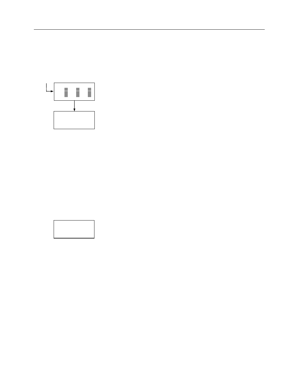
Discard change?
1:Yes 2:No
Press 1 or 2 key
Automatic mapping
BLK= 1 CP = 1 CAL= 0
CN = 1 CO = 0 SMP=93
CW = 0 QC = 0 REP= 1
Plate auto-mapping
completed