Implement lift switch adjustment, Planting depth, Implement lift switch adjustment planting depth – Great Plains NTA3007HD Operator Manual User Manual
Page 88
84 NTA907HD or NTA3007HD
166-207M
04/04/2011
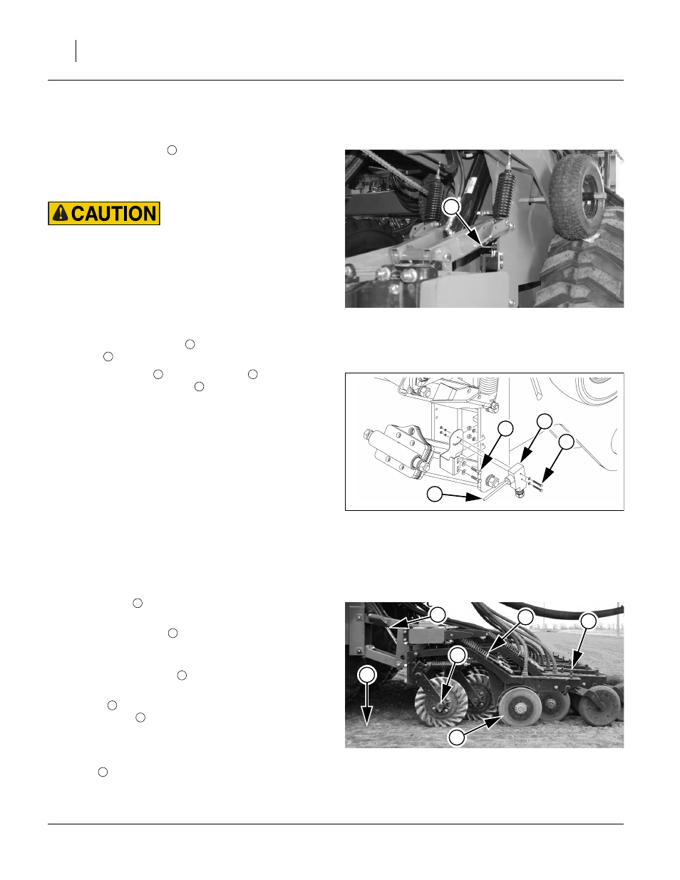
Implement Lift Switch Adjustment
Refer to Figure 89 and Figure 90
An implement lift switch
on the drill turns seed meter-
ing off when the implement is raised. To adjust the switch
activation height, first locate the lift switch on the imple-
ment (center section, right parallel arms).
Do not place any part of body under implement while making
adjustments.
Wings must be tilted down, and may be folded forward to
ease access to the switch. Lower the openers until at a
height where seeding should start (usually just above
ground). Turn off the tractor and remove the key.
Securely support center section sub-frame at this height
with jack stands or blocks.
Loosen switch pivot screws
. Adjust switch angle so
that toggle
is level, or slightly tilted up to the rear.
Loosen bracket bolts
and slide switch
up or down
until the flexible switch toggle
is just past the point at
which the switch is activated (flexible switch toggle
deflected down).
Note: The implement lift switch has three wires (black,
red and green). In order for the switch to work prop-
erly, the correct two leads must be connected to the
lift switch extension cable.
The extension cable black lead always connects to
the switch black wire.
The extension cable red lead must connect to the
switch red wire.
Planting Depth
Seed placement depth is affected by:
• soil conditions
, which can require adjustments to all
of the following;
• press wheel T-handle
which controls opener disk depth relative to press
wheels;
• (optional) coulter depth
the soil ahead of the opener disks;
• hydraulic
down-force (page 85) and
row unit spring
down-force (page 95),
which needs to be high enough for disks to open a fur-
row, but not so high that press wheels run deep or
openers tilt forward and run too deep; and,
• opener
wear (page 95), which over time can cause
established T-handle settings to be too shallow.
Null4:
Figure 89
Lift Switch Location
29475
2
1
2
3
Null4:
Figure 90
Lift Switch Adjustment
29436
1
2
3
4
4
1
4
Null4:
Figure 91
07HD Coulter and Row Unit
29419
1
2
3
4
5
6