Auger direction valve – Great Plains NTA3007HD Operator Manual User Manual
Page 56
52 NTA907HD or NTA3007HD
166-207M
04/04/2011
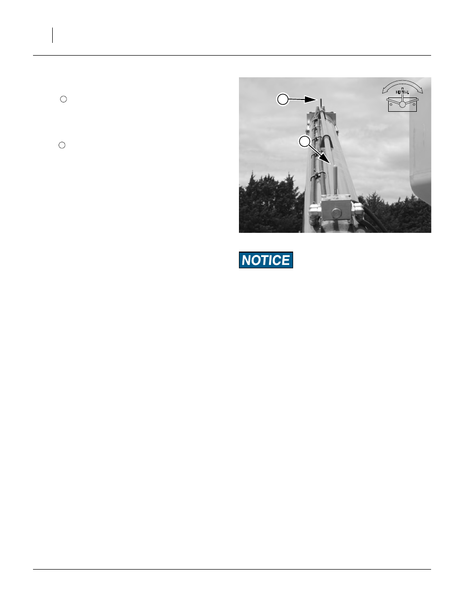
Auger Direction Valve
Refer to Figure 60
A valve
toward the inlet end of the auger tube controls
the direction of auger helicoid screw rotation.This valve is
“center off”.
To allow flow control by an operator at the outlet end, the
control handle for the valve has an extension and second
handle
.
Use this valve as the Start-Stop and Forward-Reverse
control for the auger. Set the valve to center-Off when not
moving material at the moment.
4.
With the direction control valve OFF, and
the selector valve to AUGER,
activate the tractor auger/fan hydraulic circuit by set-
ting the lever to Extend.
Note: The auger circuit is reversing. The tractor circuit
may be placed into Extend or Retract. However, if
the tractor circuit placed into Extend, this provides
a consistent experience for the auger operator, and
reduces the risk of reverse fan operation.
5.
Gradually move the handle away from center-OFF.
Note the direction of auger helicoid movement.
When moving material, adjust speed as needed,
When auger operations are completed:
6.
Set the auger direction control valve to center-OFF.
7.
Shut down tractor hydraulics, or set the auger/fan cir-
cuit to Neutral or Float.
8.
Set the auger/fan selector valve to FAN.
Null4:
Do not make sudden or full-stroke movements of the controls
with the circuit active. A circuit capable of operating the fan
has enough hydraulic flow to damage the auger motor.
Figure 60
Auger Direction Valve
26404
1
2
1
2