And 3-point height, Manual gauge wheel height, 86 and tr – Great Plains NP30A 30-foot Operator Manual User Manual
Page 90
86
NP30A or NP40A
Great Plains Manufacturing, Inc.
407-502M
2014-05-20
2- and 3-Point Height
This applies to 2-point and 3-point applicators only.
Center section tool bar height is set by the tractor hitch.
Wing end tool bar height is set by independent gauge
wheels on each wing end.
1.
Move to smooth level ground with soil as similar as
possible to field conditions. Set tractor brakes.
2.
Using grease pen or similar, mark the desired soil
level on a knife or tine near the left outside row, but
not in the tire track (knives or tines in tracks run
shallower than other rows).
3.
Raise the applicator (page 52 or page 51).
4.
Unfold the applicator (page 58).
5.
Lower the applicator until the center section knives
or tines are just above the ground. Set circuit to
Neutral to hold this height.
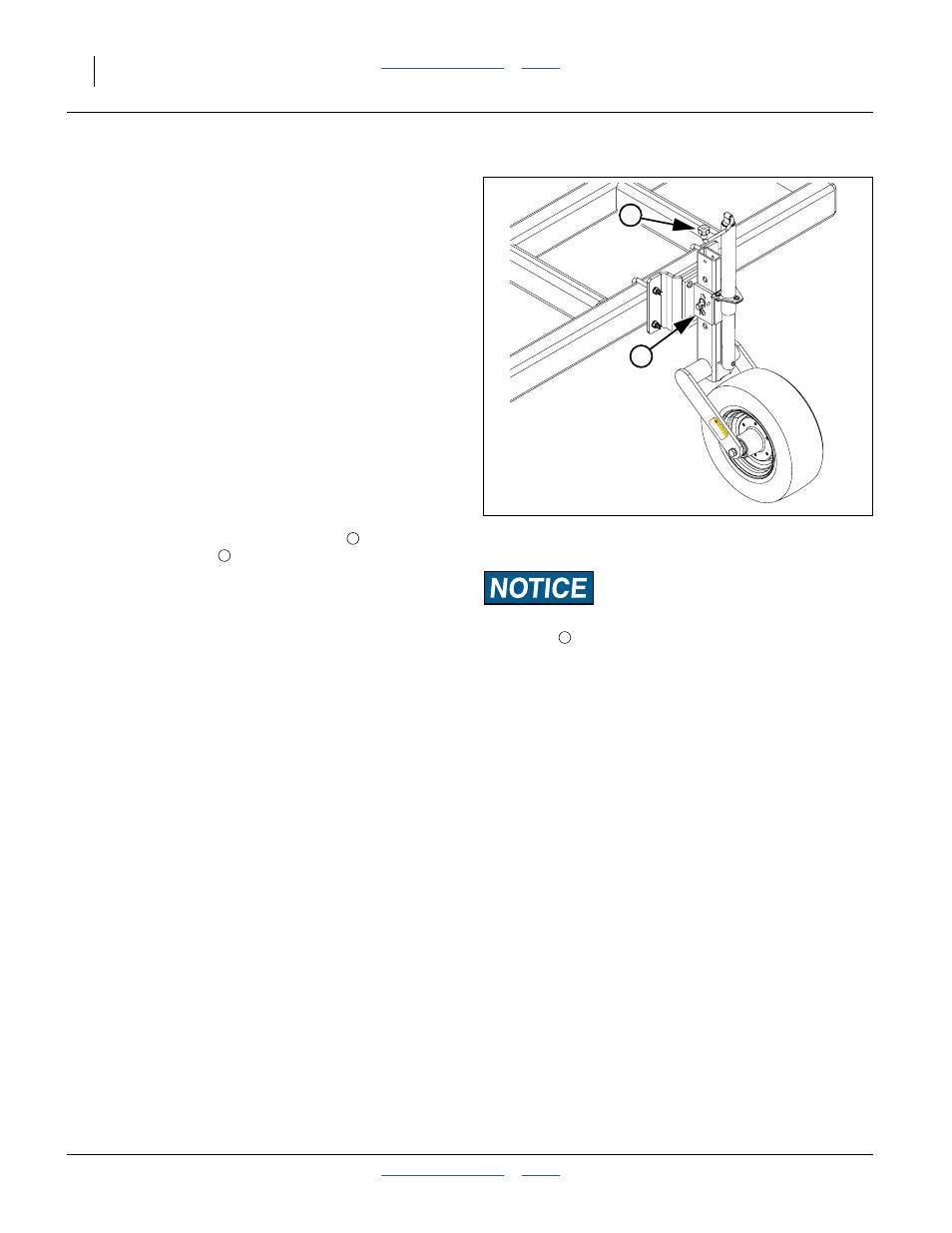
Manual Gauge Wheel Height
Refer to Figure 67
6.
At each gauge wheel, use the crank
to remove
tension at the pin
. Remove the pin.
7.
Adjust the wheel height to bring the wing knives or
tines to the same height as the center section knives
or tines (just above the ground).
8.
Lower the applicator (page 52 or page 51) until the
center section knives or tines are resting on the
ground.
9.
Use the gauge wheel cranks to raise the wheels until
the clearance under the bottom of the tires equals
the desired knife/tine depth (to shoe bottom).
10. Use the crank to bring one set of mount and tube
holes into alignment. Insert and secure pins.
11. Pull forward, lowering the center section until all
sections are level from left to right.
12. Measure the depth at which the knives or tines are
running. If the knives or tines are at the desired
depth, no further adjustment is necessary. Skip to
step 14.
13. If wing tip height needs to be adjusted, raise the
applicator slightly as needed, remove pins and
adjust gauge wheel height. Re-pin. Recheck per
step 12.
14. Adjust hitch height until center section knife or tine
depth matches wings, and applicator is level.
Capture this hitch setting.
Equipment Damage Risk:
Use the pin
. Crank the tube up against the pin. Wheel loads
transmitted to the crank can damage the crank.
Note: Turn crank clockwise to raise applicator (lower
wheel), and counterclockwise to lower applicator
(raise wheel).
Note: At maximum height, the knives or tines are off the
ground. This configuration is useful for unfolded
parking, storage and service.
Make a record of the setting needed for field
height prior to setting for maximum.
Figure 67
Gauge Wheel Adjustment
31732
6
83
8-59
5C
T
or
q
ue wheel bolts
t
o 120 lb-ft.
Ma
x
imu
m
in
flation
p
res
su
re
of t
ires
is
90
p
s
i.
T
o
Av
oi
d In
ju
ry
or
Ma
c
h
ine Dam
a
ge
f
ro
m
Impr
oper
Ti
re
In
flation
o
r T
o
rqui
n
g o
f W
h
ee
l B
olts
:
CA
UTION
6
5
5
6