Monitor operation, Field application, Starting nh3 tank flow – Great Plains NP30A 30-foot Operator Manual User Manual
Page 77: Monitor operation field application, Starting nh, A65 a18
Great Plains Manufacturing, Inc.
Applicator Operating Instructions
73
2014-05-20
407-502M
Monitor Operation
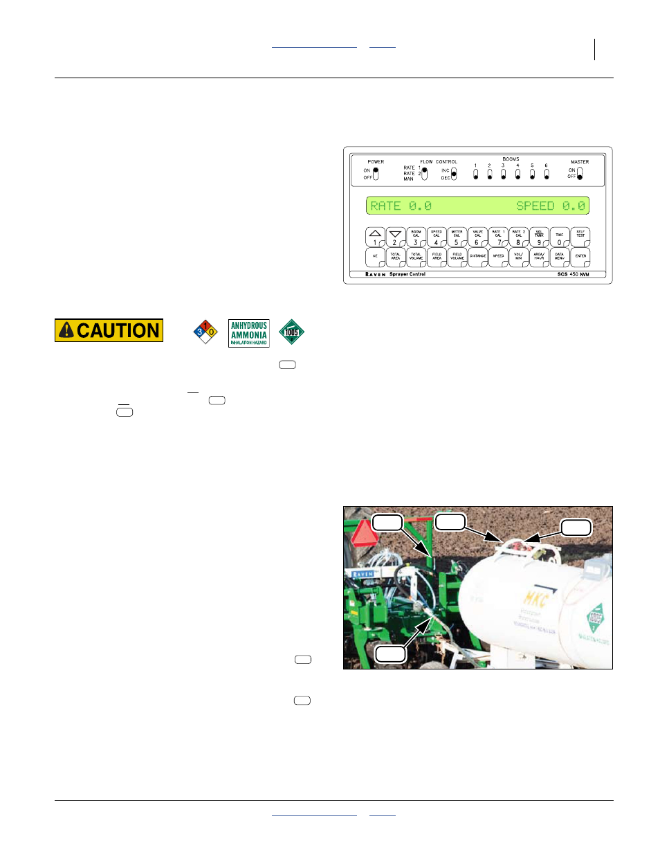
Refer to Figure 61
The optional SCS 450 console monitors NH
3
flow,
monitors field speed, and operates the (rate) control
valve to deliver anhydrous ammonia at your desired rate.
Once setup for the applicator and preferences, and
configured for the rates/limits, the monitor is typically
used in the “RATE 1” or “RATE 2” FLOW CONTROL
modes.
POWER: must be ON
FLOW CONTROL: as desired
BOOMS: 1 or BOOMS 1,2&3 ON,
all others don’t-care (suggest OFF)
MASTER: OFF except when in field and in ground
POWER Switch: Ammonia Release Hazard:
The MASTER switch only controls the On/Off valve
if the
POWER switch is ON (and power is supplied to the console).
If you turn the POWER switch off with the MASTER and any
BOOM switch on, the On/Off valve
remains OPEN, the
Control Valve
may be open and ammonia may continue to
flow from the nurse tank to the knives or tines.
See SCS 450 manual for monitor operation details.
Field Application
Starting NH
3
Tank Flow
13. Spot the applicator at the start of the first pass.
14. If the tractor has adequate power, lower the knives or
tines into the ground and pull forward to fully seat
them.
Refer to Figure 61
15. Check console MASTER switch OFF.
16. Put on your chemical gloves and goggles.
Refer to Figure 62
17. Check all applicator and nurse tank valves closed (all
in-line valves and all bleed valves).
18. From up-wind, open the tank withdrawal valve
.
Check for leaks and open valves.
Expect NO ammonia odor at this time.
19. Open the applicator emergency shut-off valve
.
Check for leaks and open valves.
Expect NO ammonia odor at this time.
Figure 61
Typical Line-Up Screen
31588
Figure 62
Open Valves
31566
A61a
A61b
A65
A18
A65
A18