Lift-assist valve setup, Console installation, Lift-assist valve setup console installation – Great Plains NP30A 30-foot Operator Manual User Manual
Page 159
Great Plains Manufacturing, Inc.
Appendix B - Initial Setup
155
2014-05-20
407-502M
Lift-Assist Valve Setup
This applies to 2-Point applicators only.
1.
Locate the one-way restrictor valve
at the tee that
supplies the rear cylinder base ends.
2.
Turn the knob fully counterclockwise.
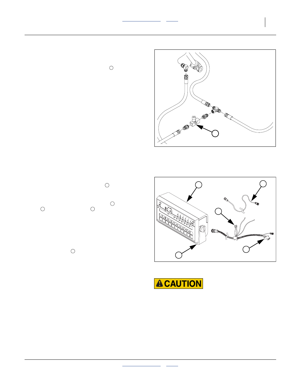
Console Installation
Refer to Figure 100
The applicator’s optional Raven SCS 450 flow controller
system includes one or two consoles
that need to be
mounted in the cab of the tractor to be used with the
applicator.
Each monitor includes cables for power
, speed
sensor
and sensor harness
. Installation
instructions are found in the included 016-0159-831
Raven SCS 450 Installation, Operation and Service
manual manual.
Power color code is:
+ positive: red
- negative: black
The included bracket
requires customer-supplied
fasteners.
Before first field use of the SCS 450, it must be
programmed with data specifying the system
configuration, consisting of various “CAL” numbers and
user elected “RATE” numbers. See the Raven SCS 450
manual for display interpretation, and see the manual of
or the Calibration Card for the keystroke sequence for
setting each of these values.
MetaData: This data is retained as long as the SCS 450
remains connected to battery power. If power is removed
for electrical work, long term tractor parking or welding,
the data is lost and must be re-entered.
Figure 99
Lift-Assist Valve
31612
1
Transport and Field Safety Risk:
Mount the module so it is easy to monitor during application,
but does not interfere with safe operation of the tractor in the
field or on public roads.
Figure 100
SCS 450 Tractor Components
27271
1
3
4
2
5
1
2
3
4
5