Plumbing diagrams, System elements – Great Plains NP30A 30-foot Operator Manual User Manual
Page 146
142
NP30A or NP40A
Great Plains Manufacturing, Inc.
407-502M
2014-05-20
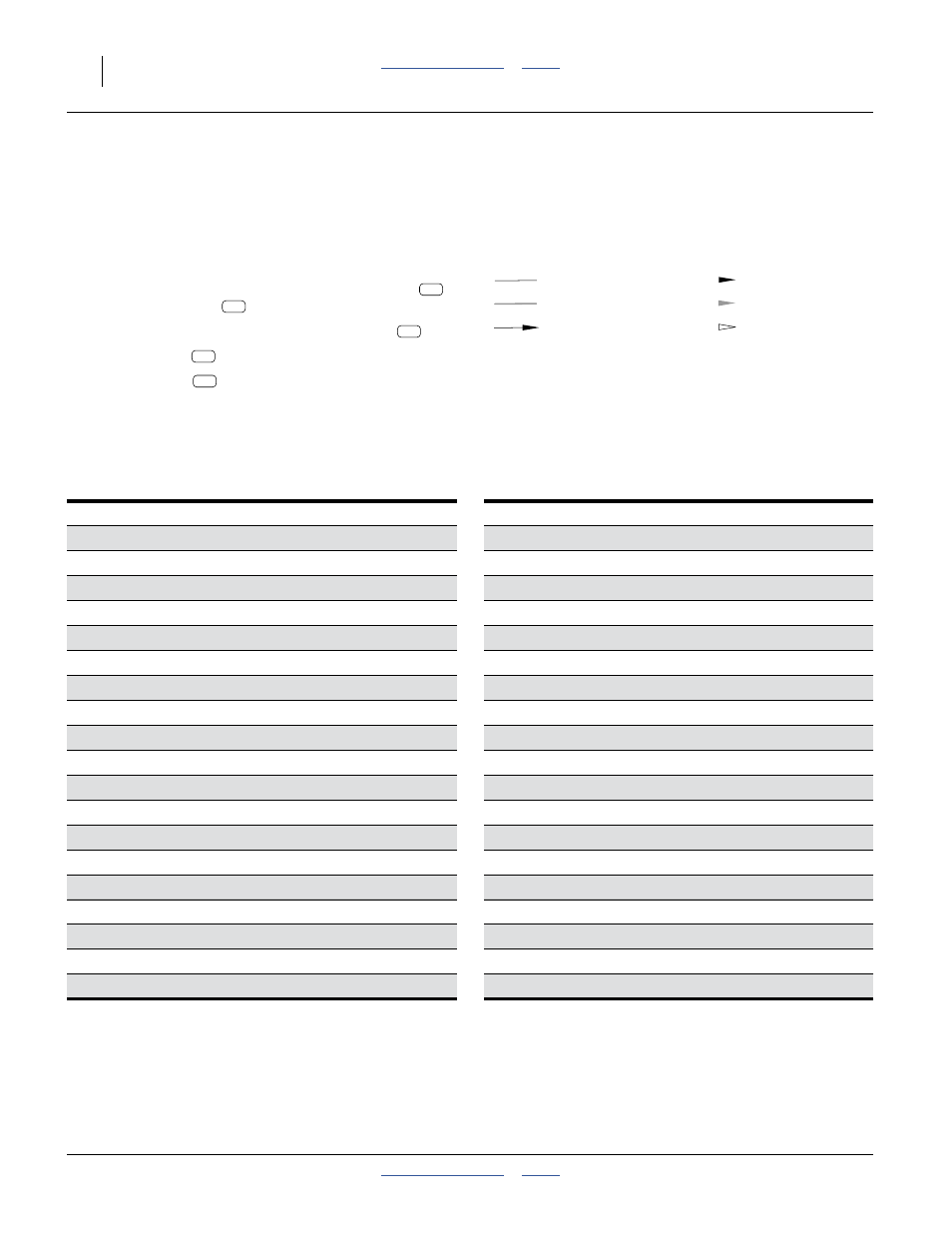
Plumbing Diagrams
See page 22 for a narrative.
System Elements
The dual-cooler systems (page 145 and 146) differ from
the single-cooler systems (page 143 and 144) as follows:
• The inflow from the tank is split after the strainer
feeding two coolers
• Cooler outlets are merged prior to flow meter
• Refrigerant tap
is split.
• Two more tines
are dual-tube for vapor dispersal.
The section-control systems (pages 144 and 146) differ
from the single-section systems as follows:
• There is a check valve, bleed valve and 3-way flow
divider prior to section flow dividers.
• Each section flow divider has a shut-off solenoid valve.
A11. Acme cap
A32. Refrigerant Tap
A13. Coupler Inlet Bleed Valve
A15. Breakaway Hydrostatic Relief Valve
A35. Section Control Check Valve
A16. Coupler Outlet Bleed Valve
A36. Section Control Bleed Valve
A37. Section Control Relief Valve
A18. Emergency Shut-off Valve
A38. Section Flow Divider
A39. Section Shut-Off Valves
A20. Strainer Magnets
A21. AccuFlow™ Super Cooler (Heat Exchanger)
A41. Flow Divider Manifold Inlet
A42. Flow Divider Pressure Gauge
A23. Cooler Hydrostatic Relief Valve
A43. Flow Divider Outlet
Legend:
For more details on components A11 through A49, see
“Systems Overview” on page 22.
Liquid NH
3
Liquid Flow
NH
3
Vapor
Vapor Flow
Direction of Flow
Exception Flow
A32