Gauge wheel lock channels, Wing lock channels, Gauge wheel lock channels wing lock channels – Great Plains NP30A 30-foot Operator Manual User Manual
Page 49
Great Plains Manufacturing, Inc.
Applicator Operating Instructions
45
2014-05-20
407-502M
Gauge Wheel Lock Channels
In routine use, install only the center section locks. For
maintenance, install all four. Installing the left wing lock
requires disabling the hydraulic depth stop.
Falling Hazard:
Do not climb or stand on tires or wheels. Even at full extension
on level ground, tires may not be in firm ground contact. They
could spin without warning. A fall could result in serious
injury.
Refer to Figure 24 and Figure 25
To install cylinder stops:
1.
Fully raise applicator (page 48). Set lift circuit to
Neutral.
2.
Install lift-assist locks (page 44).
3.
At each section lift cylinder to be locked, remove
cotter pin and lock pin
. Remove lock channel
from storage location
.
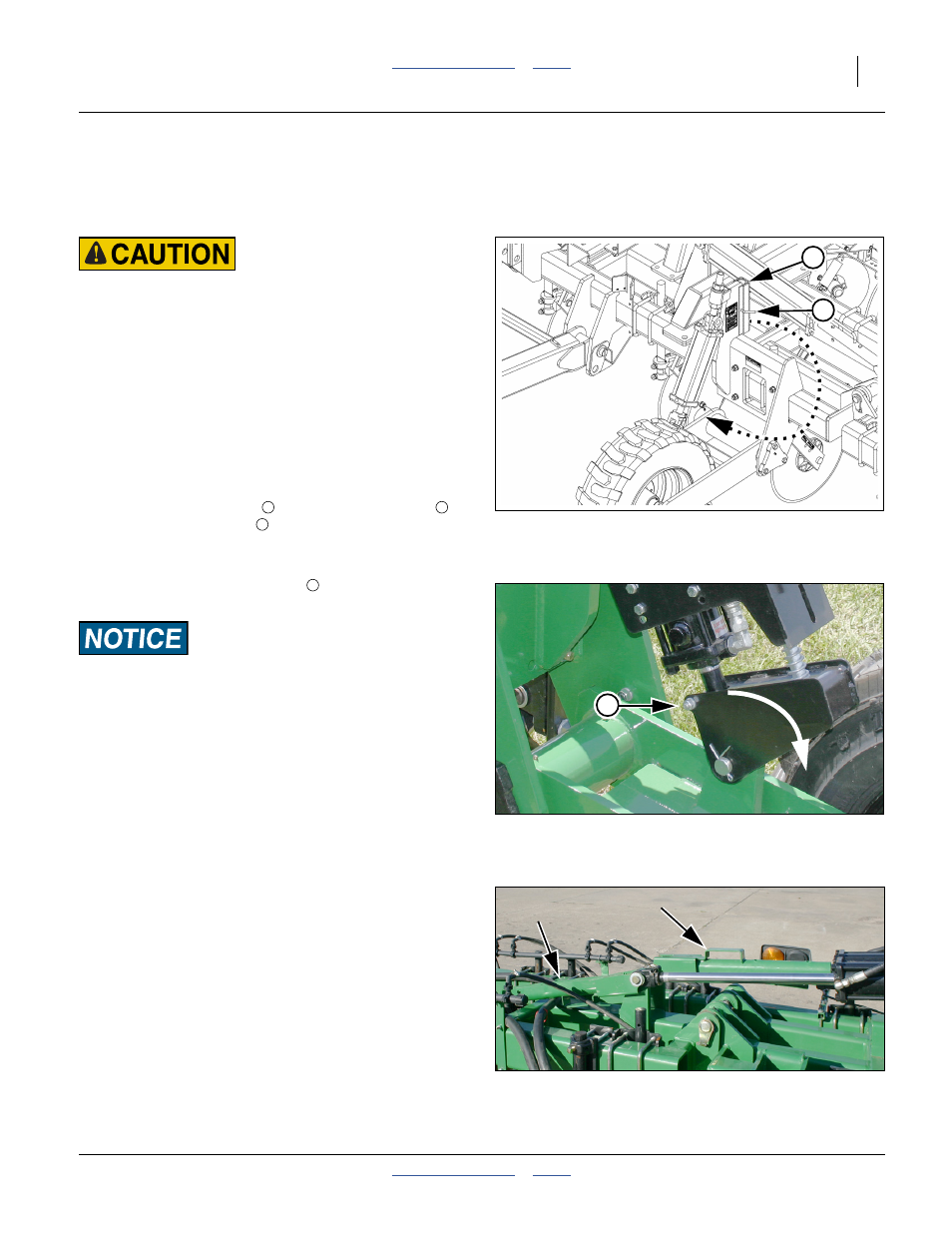
Refer to Figure 26
4.
If locking for maintenance, at the left wing lift
cylinder, remove the rear pin
of the depth stop
clevis. Swing the clevis forward and down.
Machine Damage Risk:
Do not install a lock channel on the depth stop cylinder unless
the clevis has been rotated clear of the cylinder rod. Lowering
the applicator onto a lock channel with the clevis in place will
damage the clevis.
5.
Place a lock channel on the lift cylinder rod of each
cylinder to be locked.
6.
Re-install locking pin and secure with cotter pin.
7.
Lower fertilizer applicator onto lock channels.
8.
Set lift circuit to Float.
Wing Lock Channels
Refer to Figure 27
These lock channels are only present on 2012- NP40A,
NP30A, NP3000 2-point with lift assist and 3-point
models. They enable a partial “gull wing” fold during field
lift. On 2013+ models, this function is controlled by
solenoid valves.
See page 59 for operation.
3
1
Figure 25
Forward Lift Cylinder Lock Channel
31609
_200%
3
1
2
4
Figure 26
Disengage Hydraulic Depth Stop
31742
4
Figure 27:
Wing Lock Channels
31620