3n: interconnect wsmbs, 3n: route drill harness, 3n: route front hitch harness – Great Plains NTA3510 Installation Instructions User Manual
Page 8: 3n: route wing harnesses, Ud r l
Great Plains Mfg., Inc.
8
Blockage Monitor Kits
168-414M
10/29/2008
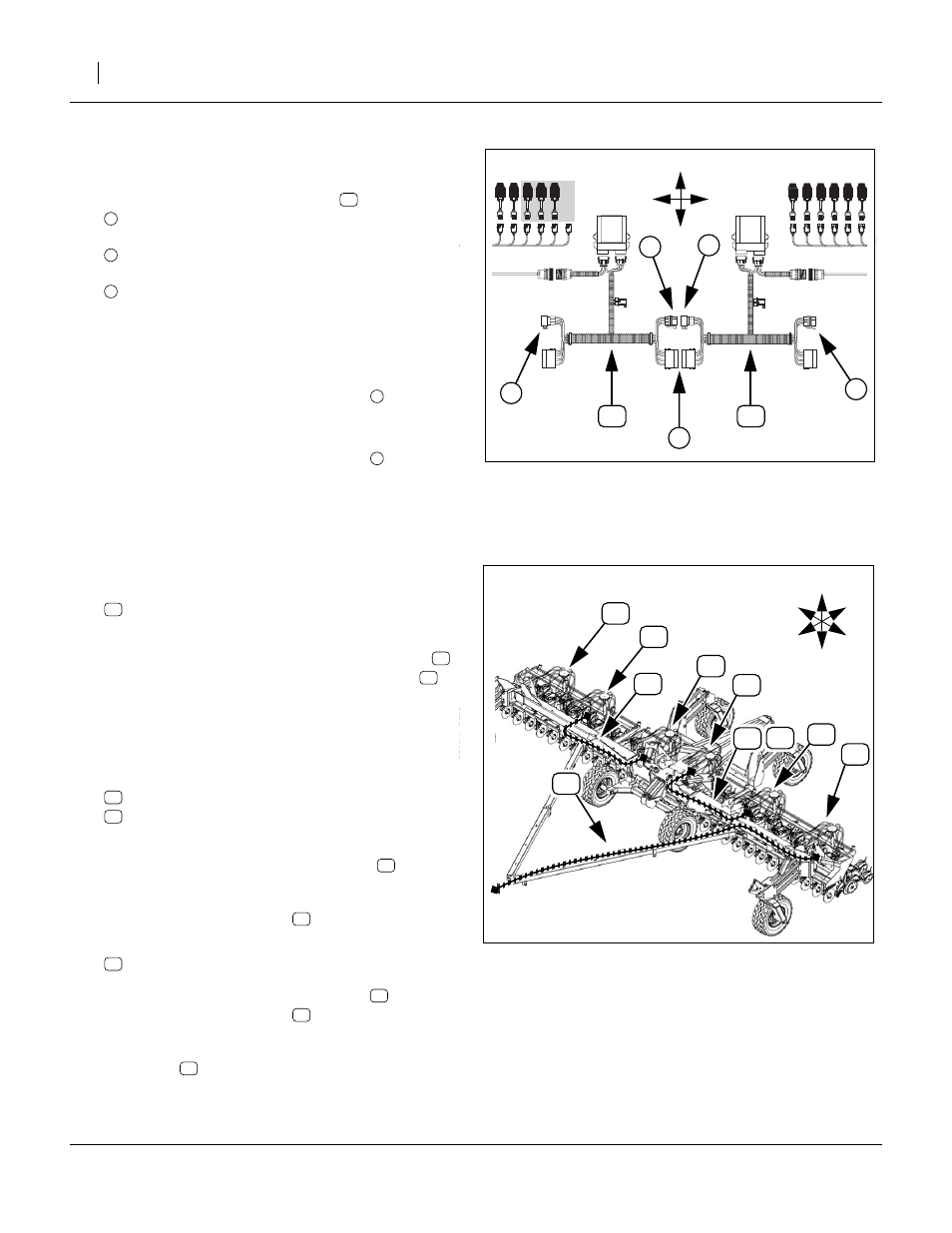
3N: Interconnect WSMBs
Start with the left wing.
27. At the left wing WSMB harnesses
, interconnect
the female (receptacle) of left (outer) CAN bus
with
the male (plug) end of the mid-wing CAN bus.
Also connect the
power receptacle and plug
Note: The unconnected mid-wing CAN bus connector, at
right (near drill center) must be a receptacle.
28. At drill center, interconnect the center WSMB har-
nesses as shown in Figure 14, so that the free end
of the CAN bus at right is a receptacle
29. At the right wing, interconnect the wing WSMB har-
nesses as shown in Figure 14, so that the free end
of the CAN bus at right is a receptacle
3N: Route Drill Harness
When routing harness extensions, allow slack at towers for raising and lowering.
3N: Route Front Hitch Harness
Refer to Figure 15 and Figure 16 on page 9
30. Locate the rear end of:
Route the free rear end of this cable to Tower 1
,
and connect it to the Tower 1 WSMB harness
.
Secure hitch harness and Tower 1 WSMB harness
with ties.
3N: Route Wing Harnesses
31. Select one saved and one new:
467980141 10’ EXT HARNESS
467980141 10’ EXT HARNESS
Plug cables together. Connect plug end of the
assembly to WSMB harness at Tower 2
(left mid-
wing). Route the harness through the hoop at the
left wing pivot. Connect the receptacle end to the
WSMB harness at Tower 3
(left side of center).
32. Select one new:
Connect the plug end of the extension
WSMB harness at Tower 4
(right center). Route
the harness through the hoop at the right wing pivot.
Connect the receptacle end to the WSMB harness
at Tower 5
(right mid-wing).
Figure 14: 3N:
Left Wing Interconnect
28201
U
D
R
L
3
3
Figure 15
Blockage Harness Route (1 of 2)
28443
T2
T1
T3
T4
T5
T6
U
D
F
B
L
R
T1
T2
T3
34
T4
T5