Tools required, Notations and conventions, Call-outs – Great Plains NTA3510 Installation Instructions User Manual
Page 2: Mount and wsmb orientation, Mount and wsmb, Orientation
Great Plains Mfg., Inc.
2
Blockage Monitor Kits
168-414M
10/29/2008
Tools Required
• Current Operator manual:
3N4010HDA
196-444M
CTA4000
160-269M-A
CTA4000HD
160-037M
NTA3010
160-219M-A
NTA3510
160-219M-A
• Updated Parts manual:
3N4010HDA
196-444P
CTA4000
160-269P
CTA4000HD
160-037P
NTA3010
160-219P
NTA3510
160-219P
• tractor or hydraulic power source, and;
• basic hand tools, including a power drill and
11
⁄
16
to
3
⁄
4
in (17-19mm) hole saw.
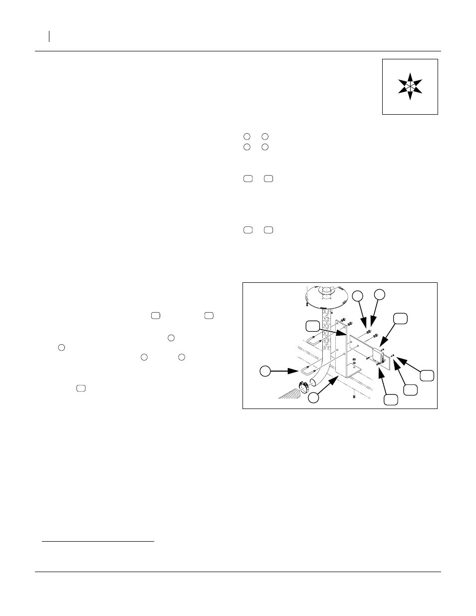
Mount and WSMB
a
Orientation
The kit includes a mounting plate
for
each tower.
The plate attaches to the tower mount
, at an existing
U-bolt
located just above the bend in the tower tube,
and under the existing washer
and nut
orientation (left, right, front or back) is described in the
detailed steps.
The WSMB
mounts to the tower side of the plate, with
mount ears flat against the plate, and connectors facing
down.
a. WSMB: DICKEY-john Working Set MemBer module
Notations and Conventions
“Left” and “Right” are facing in the
direction of machine travel. An orienta-
tion rose in the line art illustrations
shows the directions of Left, Right,
Front, Back, Up, Down.
Call-Outs
to
,
to
Single-character callouts identify compo-
nents in the currently referenced Figure or
Figures. These numbers may be reused for
different items from page to page.
to
Two-digit callouts in the range 11 to 40 refer-
ence new parts from the new parts list on
page 40. The descriptions match those on
the parts, bags or cartons, and in your
updated Parts Manual.
to
Two-digit callouts in the range 91 to 98 refer-
ence existing parts from the list on page 41.
The descriptions match those your Parts
Manual.
U
D
L
R
B
F
1
9
a
z
Figure 2
Typical Module Mount
27058
3
2
1
4
4