Nta35 mount row harnesses, Nta35: sensors to harnesses – Great Plains NTA3510 Installation Instructions User Manual
Page 25
Great Plains Mfg., Inc.
Installation Instructions
25
10/29/2008
168-414M
NTA35 Mount Row Harnesses
Start with Tower 1 (left wing, left tower).
16. Select one new:
Observe that the assembly has:
one large connector (for the WSMB);
a sealed weather-cap module; and,
12 or 16 row sensor connectors, numbered
“ROW 1” through “ROW 12”.
Note: There may be more sensor leads than drills rows.
“ROW 9” through “ROW 12” are unused on
NTA3510-4010
All leads are used on NTA3510-5575.
Note: Connector numbering matches harness-to-row
only on Tower 1. At connection step 19, see “Port
Assignment” table on page 36 or 37.
17. Select one:
800-082C CABLE TIE .31X21.5 6DIA 120LB
At the tower, position the weather-cap module
:
- lead bundle down,
- just under the upper U-bolt
, and;
- on the same side as the WSMB
.
Secure the module with tie
weldment and mounting plate.
18. Repeat step 16 and step 17 for Tower 2 through
Tower 5.
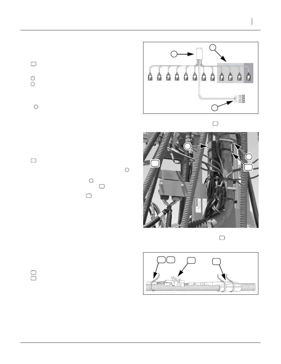
NTA35: Sensors to Harnesses
Start with opener 1 (left opener, left wing).
19. Using the table on pages 38 or 39, determine the
Harness lead (“ROW”) to tower Port assignment.
Isolate each lead from the bundle, and plug the
assigned harness lead and sensor cable together.
20. Select one tie from either:
110110050 TY WRAP BUNDLE 50-14"
110110099 TY WRAP BUNDLE 100-14"
Tie the harness lead to the same seed hose as its
assigned sensor. Tie about 1in (2.5cm) behind the
cable sheath
21. Repeat step 19 and step 20 for each port on the
tower, and then for each tower. One or four leads
per tower are not connected. Excess cable is tie-
wrapped at step 23.
Figure 56: NTA35:
Row Harness
28198
1 2 3 4 5 6 7 8 9 10 11 12
Figure 57: NTA35:
Install Row Harness
28199
Figure 58: NTA35:
Row Harness to Sensor
28196