Cta blockage harness diagram, Figure 32, Fb r l – Great Plains NTA3510 Installation Instructions User Manual
Page 15
Great Plains Mfg., Inc.
Installation Instructions
15
10/29/2008
168-414M
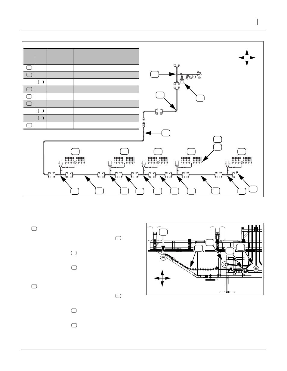
CTA Blockage Harness Diagram
Refer to Figure 32 and Figure 33
32. Select one new:
Connect one end to the WSMB harness
Tower 1.
Route the harness
to Tower 2, following the
large seed inlet hose.
Connect extension
to WSMB harness at
Tower 2. Secure extension with ties.
33. Select one new:
Connect one end to the WSMB harness
Tower 2.
Route the harness
to Tower 3, following the
nearest cross-tube.
Connect extension
to WSMB harness at
Tower 3. Secure extension with ties.
Harness ID
Callout
Part
Number
Description
New
Ex.
467980817S1 WSMTII GP AIR CART MODULE
Figure 32
CTA-4000/HD Harness Block Diagram
28431
F
B
R
L
T1
T2
T3
T4
T5
Figure 33: CTA:
Tower 1 to Towers 2 and 3
28436
T1
T2
F
B
R
L
T3
This manual is related to the following products: