Nta35 blockage harness diagram, Figure 62, Fb r l – Great Plains NTA3510 Installation Instructions User Manual
Page 27
Great Plains Mfg., Inc.
Installation Instructions
27
10/29/2008
168-414M
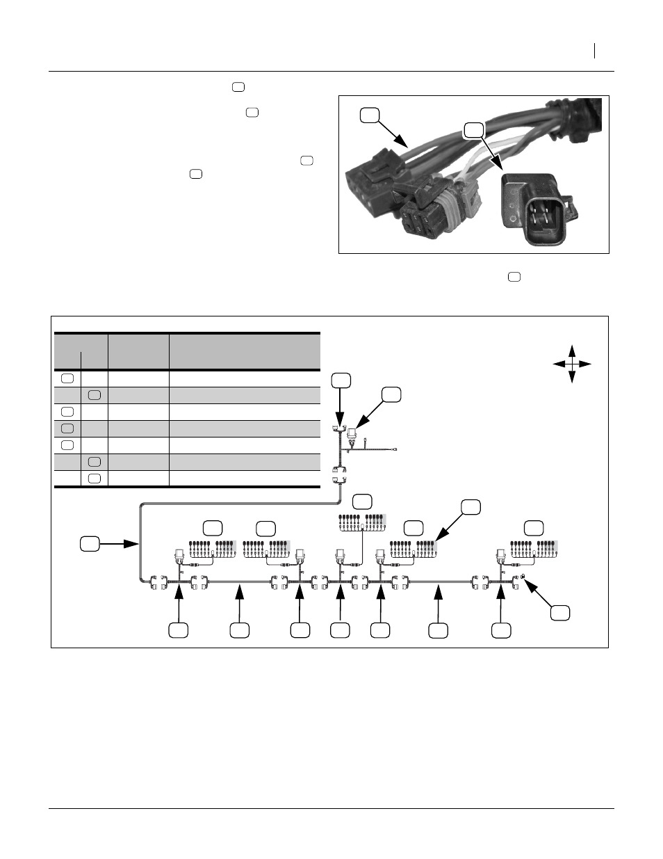
29. Remove and save the terminator
.
Connect the 20ft harness extension
(two connectors).
Refer to Figure 62 and Figure 63
30. At Tower 5, plug the saved CAN bus terminator
into the WSMB harness
NTA35 Blockage Harness Diagram
Figure 62: NTA35:
CAN Terminator
28429
Harness ID
Callout
Part
Number
Description
New
Ex.
PLNTR CNTRL OUTPUT MODULE(POM)
DJ 2SOL YP24LIFT/HITCH FCM HRN
Figure 63
NTA-3510 Harness Block Diagram
28441
F
B
R
L
T1
T2
T3
T4
T5
This manual is related to the following products: