Nta35: install wsmb harnesses, Nta35: interconnect center wsmbs, Apped at step 23 – Great Plains NTA3510 Installation Instructions User Manual
Page 26: Ud l r, Ud r l
Great Plains Mfg., Inc.
26
Blockage Monitor Kits
168-414M
10/29/2008
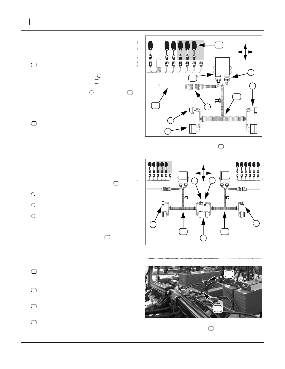
NTA35: Install WSMB Harnesses
Start with Tower 1 (left wing, left tower)
22. Select one:
Join the row harness connector
connector on the row harness
.
Plug the WSMB connectors
These connectors are not interchangeable, and are
keyed to ensure correct insertion.
23. Select two:
800-082C CABLE TIE .31X21.5 6DIA 120LB
Coil up excess row harness leads and tie the bundle
to the tower, above and below the lower U-bolt.
24. Repeat step 22 and step 23 for each tower.
NTA35: Interconnect Center WSMBs
The center section Towers 2, 3 and 4 are close enough
that their WSMB harnesses are directly interconnected.
25. At the center section WSMB harnesses
for
Tower 2 and Tower 3, interconnect
the female (receptacle) of left (outer) CAN bus
with
the male (plug) end of the mid-wing CAN bus.
Also connect the
power receptacle and plug
Note: The unconnected Tower 3 CAN bus connector (at
drill center) must be a receptacle.
26. Interconnect the WSMB harnesses
for Tower 3
and Tower 4.
Refer to Figure 61, and Figure 62 and 63 on page 27
27. Select one new:
28. At the front center of the drill, locate the existing
implement WSMB:
PLNTR CNTRL OUTPUT MODULE(POM)
At the WSMB connectors, follow harness:
DJ 2SOL YP24LIFT/HITCH FCM HRN
Locate the CAN bus terminator:
Figure 59: NTA35:
WSMB Harness
28200
1
2
3
4
5
U
D
L
R
1
Figure 60: NTA35:
Center Towers Interconnect
28201
U
D
R
L
Figure 61: NTA35:
Existing WSMB
Location
28438