Fan circuit operation – Great Plains YP3025A Operator Manual User Manual
Page 47
Great Plains Manufacturing, Inc.
Operating Instructions
43
02/16/2012
401-705M
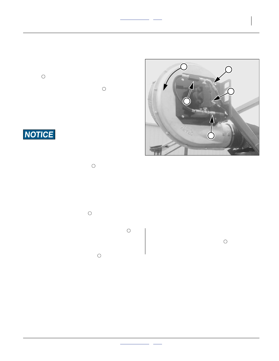
Fan Circuit Operation
See also “Fan and Adjustment” on page 61.
Refer to Figure 45
Three hydraulic hoses serve the fan, and must be prop-
erly connected for the fan to operate in the correct
direction
, at recommended speeds, and without dam-
age. See “Hydraulic Hose Hookup” on page 15.
1.
Always connect the case drain line
first.
This line protects the outer shaft seal of the hydraulic
motor. The case drain is a small line to the hitch, pro-
visioned with a specialized low-seep flat-face case
drain Quick Disconnect. Pressure spikes during
motor operation, and pressure cycles due to temper-
ature change are bled off by the case drain.
Motor Seal Damage Hazard:
Do not apply pressure to the case drain line. Do not change the
special QD connector. A restricted or sealed case drain line
will promptly result in motor seal damage.
2.
Connect the motor return line
second, to sump.
The planter includes an 1
1
⁄
16
in low back-pressure
QD coupler set. Install the receptacle on a tractor
sump port, and not at a normal remote return port.
The unusual size aids in ensuring correct connec-
tion, so that the motor return line handles high vol-
ume at low back-pressure, ensuring full motor
performance.
3.
Connect the motor inlet line
to a tractor remote
capable of the flow rates shown at “Recommended
Fan Speeds” on page 44.
4.
The fan hydraulic circuit includes a check valve
which provides a relief path for oil at motor shutoff.
The resulting low fan rpm provides strong indication
reversed connection.
Correct fan direction is shown at
.If reversed fan is
suspected, observe it during shutoff, as the direction
of motion is easier to see at lower rpms as it slows to
a stop (initial startup is virtually instantaneous, mak-
ing observation at start difficult).
Fan speed is controlled by the tractor circuit (and not the
seed monitor). Fan rpm is reported by the seed monitor
console.
You may stop the fan by setting the circuit to neutral or
float. The check valve slows the blades to a stop by
locally recirculating the oil.
Null4:
Figure 45
Hydraulics at Fan
29800
1
2
3
4
5
If the fan is connected in reverse, it may not run at all
(due to no oil source at the return connection). If oil is
present, oil bypass at the check valve
prevents the
fan from reaching operating rpms. A reversed fan is
incapable of providing sufficient air flow for planting.
5