Install press wheels, Install upper marker components – Great Plains YP3025A Operator Manual User Manual
Page 167
Great Plains Manufacturing, Inc.
Appendix B - Pre-Delivery
163
02/16/2012
401-705M
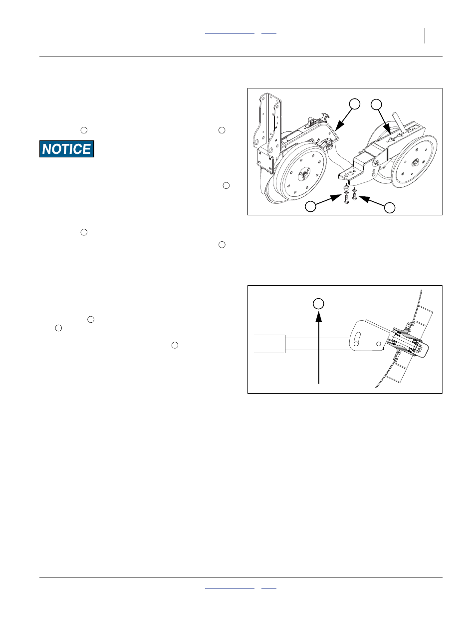
Install Press Wheels
To meet highway clearance requirements, press wheel
arms and wheels on wing rows are not factory-installed.
Remove and save the
1
⁄
2
-13x1in hex head bolt and
washer
at the back of an incomplete row unit
There are four bolts at this location. Remove only the hex head
bolts. Do not loosen or remove the square head bolts forward.
2.
Remove and save the
1
⁄
2
-13x1
1
⁄
2
in hex head bolt
,
washer, and eccentric adjuster nut.
3.
Align the
1
⁄
2
in holes in the press wheel assembly
with the
1
⁄
2
-13 tapped holes in the row unit, loosely
assemble with the
1
⁄
2
-13x1in hex head bolt and
washer
.
4.
Loosely screw in the
1
⁄
2
-13x1
1
⁄
2
in hex head bolt
washer, and eccentric adjuster nut. Rotate the
adjuster to visually align the press wheel assembly
with the row unit, and tight the adjust and both bolts.
Install Upper Marker Components
Marker disks and end tubes are removed for shipping.
Refer to Figure 140
The end tube
may be inserted into the outer marker
arm
in any of four orientations. Great Plains recom-
mends that the spindle adjustment allow the disk to pivot
back, away from the direction of travel
.
If the markers are extended for this work, also set the ini-
tial marker extension based on the row spacing.
Null4:
Figure 139
25AP Press Wheel Assembly
25383
1
2
4
3
3
4
Null4:
Figure 140
Marker Disk Spindle Orientation
11757
T
T