Dual marker speed adjustment, 12 f s s – Great Plains YP3025A Operator Manual User Manual
Page 168
164
YP3025A
Great Plains Manufacturing, Inc.
401-705M
02/16/2012
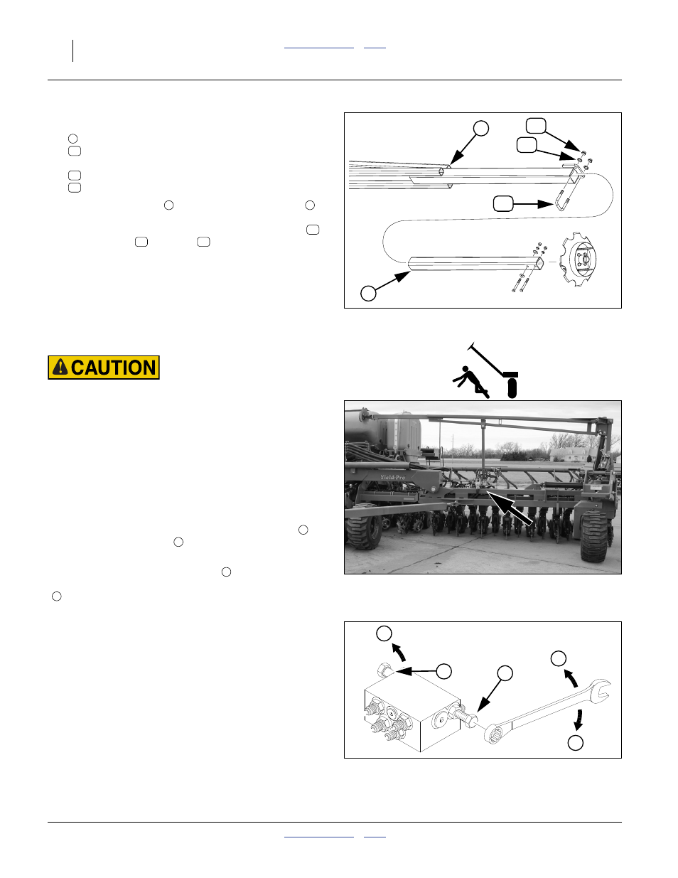
At each marker, select one each:
marker disk and tube assembly
806-110C U-BOLT 5/8-11 X 3 1/32 X 4 1/2
and two sets:
803-021C NUT HEX 5/8-11 PLT
804-022C WASHER LOCK SPRING 5/8 PLT
2.
Insert the end tube
into the outer marker arm
Insert to initial marker extension value, or about half-
way if extension is not known. Secure with U-bolt
,
lock washers
and nuts
.
Dual Marker Speed Adjustment
Overhead Sharp Object Hazard:
You may be injured if hit by a folding or unfolding marker.
Markers may fall quickly and unexpectedly if the hydraulics
fail. Never allow anyone near the planter when folding or
unfolding the markers.
Refer to Figure 142 and Figure 143
Adjust folding speed for dual markers with hex adjust-
ment screws on the sequence valve body. The valve
sequence body is located on top of the left wing frame.
Loosen jam nuts before making adjustments.
There is one adjustment screw for unfolding speed
and one for folding speed
. You can identify adjustment
screws by markings stamped in valve body.
Turn adjustment screws clockwise (
: slower) to
decrease [un]folding speed and counterclockwise
(
: faster) to increase [un]folding speed.
With tractor idling at a normal operating speed, adjust
marker folding to a safe speed. Excessive [un]folding
speed could damage markers and void the warranty.
After adjusting the folding speed, tighten jam nuts on hex
adjustment screws to hold settings.
Null4:
Figure 141
Marker Final Assembly
29177
36
1
35
34
2
36
34
35
36
35
34
Null4:
Figure 142
Marker Sequence Valve Location
29302
1
2
S
F
1
2
F
S
S
Null4:
Figure 143
Marker Speed Adjustment
14048