Brush meter adjustments, Installing brush meter plates – Great Plains YP1630F-1670 Operator Manual User Manual
Page 64
60
YP1630F
Great Plains Manufacturing, Inc.
401-832M
2012-12-27
Brush Meter Adjustments
Finger meter adjustments begins on page 58.
Installing Brush Meter Plates
A selection of seed plates are available for the brush
meter (see “Seed Plates” on page 107). Use a seed
plate specific to the crop, seed variety, and seed rate
range.
If the seed plates (or meters) need to be changed,
perform this operation before loading seed.
1.
Select 16 of the next seed plates to install. Check
that they are all for the correct seed, seed variety
and cell count. To aid in identification, there is a table
of plate characteristics on page 107.
2.
If seed is already loaded, see “Seed Unloading and
Clean-Out” on page 74.
3.
If changing from finger pickup to brush meter, see “Exchanging Meters” on page 57.
Refer to Figure 63
4.
Uncouple the meter drive (page 34), release the
hopper latch (page 74), and remove each hopper
from its row unit.
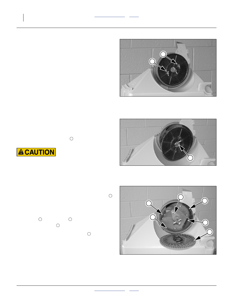
5.
Remove the two wing nuts
that secure the seed
plate to the meter shaft.
Treated Seed Hazard:
Follow material supplier recommendations carefully. Handle
the meter and plate as if they were treated seed. Use
supplier-recommended cleaning agents.Any seed treatment
build-up inside a meter is likely to be at a higher concentration
than on the actual seed.
Refer to Figure 64
6.
Pull the plate off the threaded studs, and angle one
side of the center hole over one end of the roll pin
in the drive shaft.
Refer to Figure 65
7.
With the seed plate removed, clean any debris from
inside the meter, and inspect the condition of the
brushes
and wear strip
8.
Select a new plate
. Inspect the cells for any
damage, and make sure the inside surface is clean,
so that it will seat full on the disc hub
.
9.
Orient the plate with the cell side (not the spoke side)
toward the meter shaft. Reversing the removal
process above, angle the hole over end of the drive
shaft roll pin, then the other end, and seat the plate
on the threaded studs. Secure with wing nuts.
10. Spin the plate by hand, counter-clockwise, to verify
that it sits flush and does not wobble.
11. Re-mount the hopper on the row unit and secure
with latch.
Figure 63
Brush Meter Plate Wing Nuts
28126
1
1
Figure 64
Brush Meter Plate Removal
28127
2
1
Figure 65
Brush Meter Inspection
28128
3
3
3
6
5
4
2
3
3
5