Appendix c - initial setup, Hydraulic charge and bleed, Seed monitor console installation – Great Plains YP1630F-1670 Operator Manual User Manual
Page 124: Seed monitor console quick-start
401-832M
2012-12-27
120
YP1630F
Great Plains Manufacturing, Inc.
Appendix C - Initial Setup
Hydraulic Charge and Bleed
Connect the planter to a suitable hydraulic source and
check the condition of the hydraulic systems:
“Unfolding the Planter” on page 23,
“Raising/Lowering Planter” on page 27,
“Folding the Planter” on page 28,
“Fan General Operating Information” on page 42,
“Marker Operation” on page 43
See “Bleeding Hydraulics” on page 93 if any circuits do
not operate smoothly.
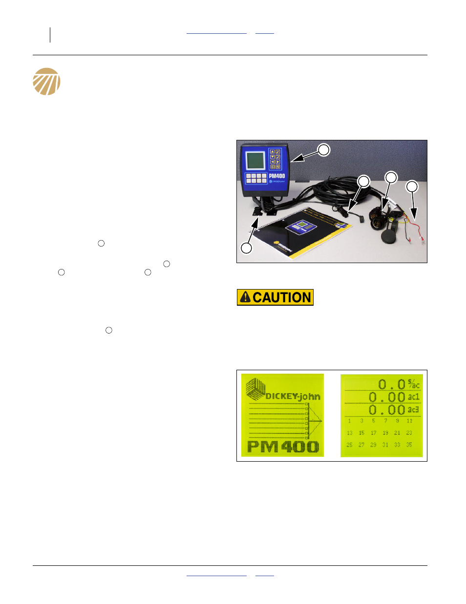
Seed Monitor Console Installation
Refer to Figure 120
The planter’s standard PM400 seed monitor system
includes a console
that needs to be mounted in the
cab of the tractor to be used with the planter.
The monitor includes cables for power
, speed
sensor
and sensor harnesses
. Installation
instructions are found in the included DICKEY-john
®
manual.
Power required is 12Vdc. Power color code is:
+ positive: red
- negative: black
The included bracket
requires customer-supplied
fasteners.
Seed Monitor Console Quick-Start
The PM400 factory defaults need to be changed to
metric mode, the row configuration of a YP1630F-1670
planter, and the speed sensing used on all models. The
pages 120 through 122 describe setting:
• metric data mode,
• planter row count,
• planter (swath-averaged) row spacing, and;
• initial speed calibration.
The monitor must be connected to +12Vdc power to
enter these settings (the monitor does not need to be
connected to the implement harness).
See the DICKEY-john
®
11001-1372 manual for setting
limits and alarms.
Transport and Field Safety Risk:
Mount the module so it is easy to monitor during planting, but
does not interfere with safe operation of the tractor in the field
or on public roads.
Figure 120
PM400 Tractor Components
32005
1
3
4
2
5
1
2
3
4
5
Figure 121
Power-Up, Operate Screens
31928
31930